Technical References
Forward Error Correction (FEC)
Forward error correction (FEC) is a method for controlling errors in data transmission that occurs over unreliable or noisy communication channels. The sender encodes the message using an error-correcting code (ECC) and does so in a redundant manner. The redundancy allows the receiver to correct errors without having to request, over a reverse channel, that the sender retransmit the lost data. For FEC to work, the sender generates an FEC parity packet for every N packets that it sends. On the sender, you configure the frequency at which FEC parity packets are generated. The receiver uses this parity packet to recover any lost packets. In this way, FEC minimizes packet loss at the receiving end, thus improving the end user’s quality of experience.
It is recommended that you configure FEC for sites that experience loss of clarity in VoIP calls and for any critical traffic that experiences packet loss. You can configure FEC to turn on automatically when links carrying the traffic become SLA non-compliant. You can use FEC along with replication to provide maximum protection and correction at sites that have multiple paths. You can use FEC to recover packets independently in situations where replication is not useful, such as at the sites with single path for transporting traffic.
When FEC is configured, it used eight packets per parity (npp) which is the frequency of the generation of parity packets.
We can illustrate the transmission quality improvement provided by FEC, as well as the overhead added by FEC, with a few calculations. Suppose you configure FEC to generate a parity packet for every three packets. The FEC overhead is 100/3, or 33%. If the path has a uniform packet loss of 5% and if you send 3 packets, without FEC the probability that all 3 packets reach the receiver is 85.74% , and this probability increases to 98.6% with FEC enabled. Suppose you now configure FEC to generate a parity packet for every 6 packets. The overhead reduces to 100/6, or 16%, and if you send 6 packets, the probability of all 6 packets reaching the destination is 95.56%. These calculations allow you to balance packet protection versus the extra bandwidth required to provide the protection.
Let’s consider a scenario where the FEC in Site 1 is configured to generate a parity packet every 3 packets. When Site 1 receives a flow that matches the policy, it starts generating parity packets. Site 2 keeps track of the sequence numbers so that it can identify lost packets. If no packets are lost, Site 2 discards the parity packet. However, if Site 2 detects a loss, when the parity packet arrives, Site 2 uses the information in the parity packet to regenerate the lost packet.
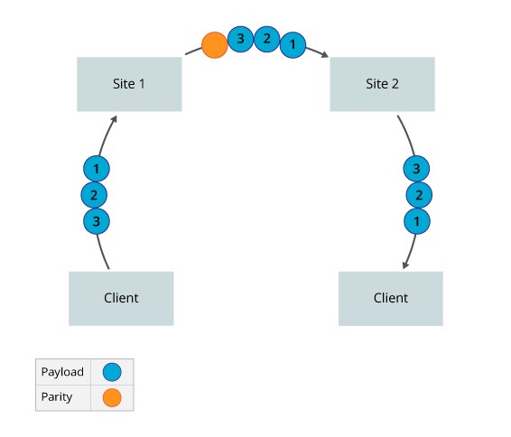
The following figure illustrates a scenario in which no packets are lost during transmission. Here, Site 1 sends 3 packets and generates a parity packet for every 3 packets. Site 2 discards the parity packet because no packets have been lost.
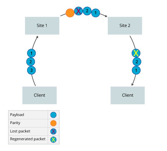
The following figure illustrates the packet loss scenario in which packets are lost during transmission. Here, Site 1 sends 3 packets and generates a parity packet for every 3 packets. However, P3 is lost during transmission. When Site 2 receives the parity packet, it regenerates the lost packet.
Packet Replication
Packet replication offers a way to improve the quality of voice traffic and other mission-critical application traffic. With packet replication, the SD WAN nodes mirror packets among two or more paths. If a packet is lost on one link, the mirrored packet is delivered on one or more secondary links. If the remote device receives more than one copy of the packet, the remote device sends the first received packet towards the LAN and drops the subsequent ones.
For replication to work, a 12-byte header is added to all replicated packets. The information in this header allows the receiving device to identify received data.
You can enable packet replication for a specific application and configure packet replication so that it turns on automatically when paths become non-compliant with configured SLA metrics. Automatically enabling packet replication only when an SLA violation occurs is useful for sites that have limited link capacity. It is recommended that you enable packet replication for sites whose audio calls are not clear.
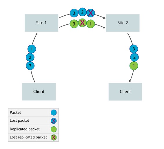
Consider a scenario where you configure Site 1 to forward the original packet to Site 2 and to replicate every packet and send the copy on an alternate path. When a flow matches the policy, Site 1 starts replicating packets. The FlexVNF at Site 2 keeps track of the packet sequence numbers so that it can identify the duplicate packets and can keep track of original packet order. Site 2 forwards the first packet it receives to the next hop or end host, and it discards any duplicate copies of the packet.
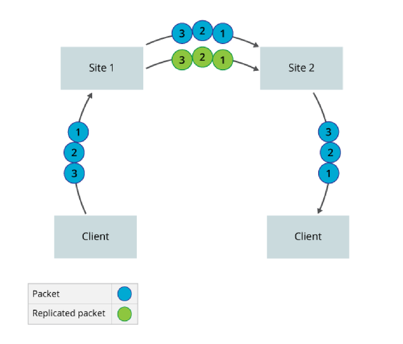
The figure below illustrates a scenario in which no packets are lost during transmission. Here, Site 1 sends three packets and a copy of each packet, sending a total of six packets. Site 2 receives all six packets. It forwards the original three packets, and it discards the copies because no packets are lost.
The figure below illustrates the packet loss scenario in which packets are lost during transmission. Here, Site 1 sends three packets and a copy of each, for a total of six packets. However, the original P1 and the copy of P2 are lost. Site 2 receives four packets and forwards all three packets that were generated by the sender. If packet replication is not enabled, Site 2 can initially forward only P2 and P3 because P1 is lost. Site 1 must retransmit P1 when the Site 2 detects that this packet has been lost. In case of TCP traffic, end host has to retransmit when it detects the loss. This can impact the performance as TCP will detect congestion and reduce the transmit window.
Worked Examples and Reference material
The use FEC to optimize the performance of network traffic and application flows can increase the bandwidth usage and CPU usage of the SD WAN hardware device.
WAN Optimization is enabled by default for WAN incoming traffic but enabled by the SD WAN portal for traffic from the LAN to the SD WAN overlay tunnels. Typical usage cases for these are TCP applications to reduce TCP retransmission. Also for real time traffic such a VoIP(RTP) where packet loss degrades the speech path.
In cases where aggregated streams traverse underlay two or more separate networks care must be taken to match the latency and jitter characteristics of any path that Packet Replicated traffic traverses.
The following is a reference to FEC and Packet Replication:
The below screen shots are examples of WAN Optimization.
REP Only. This enables packet replication only for TCP traffic that match the IP source/destination and Port on all available WAN links when for example the packet loss exceeds 18%.
Traffic steering with FEC. Enable traffic steering for IP traffic that match the IP Source/Destination, Port steer that traffic if for example the packet loss exceeds 23% to another WAN link avoiding interface 2 in the interface priority list. Then if that second WAN link experiences packet loss at the SLA value, only then will FEC be enabled.
List WAN Optimization Rule Combinations
The list of combinations available for SD WAN Portal users to set the WAN optimization rules is shown in the table below:
| Sr. No. | Recommended Policy Rule | Description | Deployment Target Cases | Behavior |
|---|---|---|---|---|
1 |
Steer traffic only |
Define an SLA associated with traffic types and priorities the WAN interfaces to be used if the metric SLA is met or violated |
Branches with multiple circuits |
By default, traffic is load balanced across multiple paths, however you can specify that the path with the best metric be preferred using interface priorities instead of configuring metrics and thresholds in an SLA profile |
2 |
Forward Error Correction Only |
Enable FEC for matched traffic on same link based on metric. |
FEC is recommended for real time traffic (RTP) as it is UDP based and not reliable. |
Always On metric: FEC packets will always be generated for the matched traffic, on the link carrying active flow. |
3 |
Replication Always |
Apply Replication to alternate link for matched traffic based on metric. |
Packet replication is recommended to improve the quality of voice( UDP) traffic and other mission-critical application (UDP/TCP) traffic. |
Always On metric: Packets will always be replicated for the matched traffic, on the alternate link. |
NAT Services
DNAT features introduce the following address translation rules
Inbound Port Mapping (Port Forwarding): Map an external IP/port to an internal IP/ port in the DMZ or LAN. This used to allow traffic from the Internet towards the DMZ or LAN on specific ports. Outbound sessions still use dynamic NAPT translation
Inbound 1:1 NAT: Map an external IP to an internal IP in the DMZ or LAN for inbound sessions. This used to allow traffic from the Internet towards a specific host in the DMZ or LAN. Outbound sessions still use dynamic NAPT
Translation
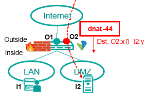
Inbound Port Mapping (PAT)
-
Map Inbound sessions from an outside destination IP/port (O2:x) to an inside IP/port (I2:y)
-
Uses Inbound dnat-44 Translation
-
Inside/outside destination port (x,y) can be same or different
-
outside destination IP (O2) can be
-
Separate IP from WAN subnet (reachable via proxy ARP)
-
IP from separate NAT Pool (reachable via external route towards CPE WAN)
-
Outbound sessions still use NAPT-44 translation Use case:
-
Expose services in Customer DMZ (or LAN) to the Internet for inbound only sessions on well-defined ports:
-
e.g. Web Server / Proxy (HTTPS), Mail Server (SMTP), Bastion Host
(SSH)
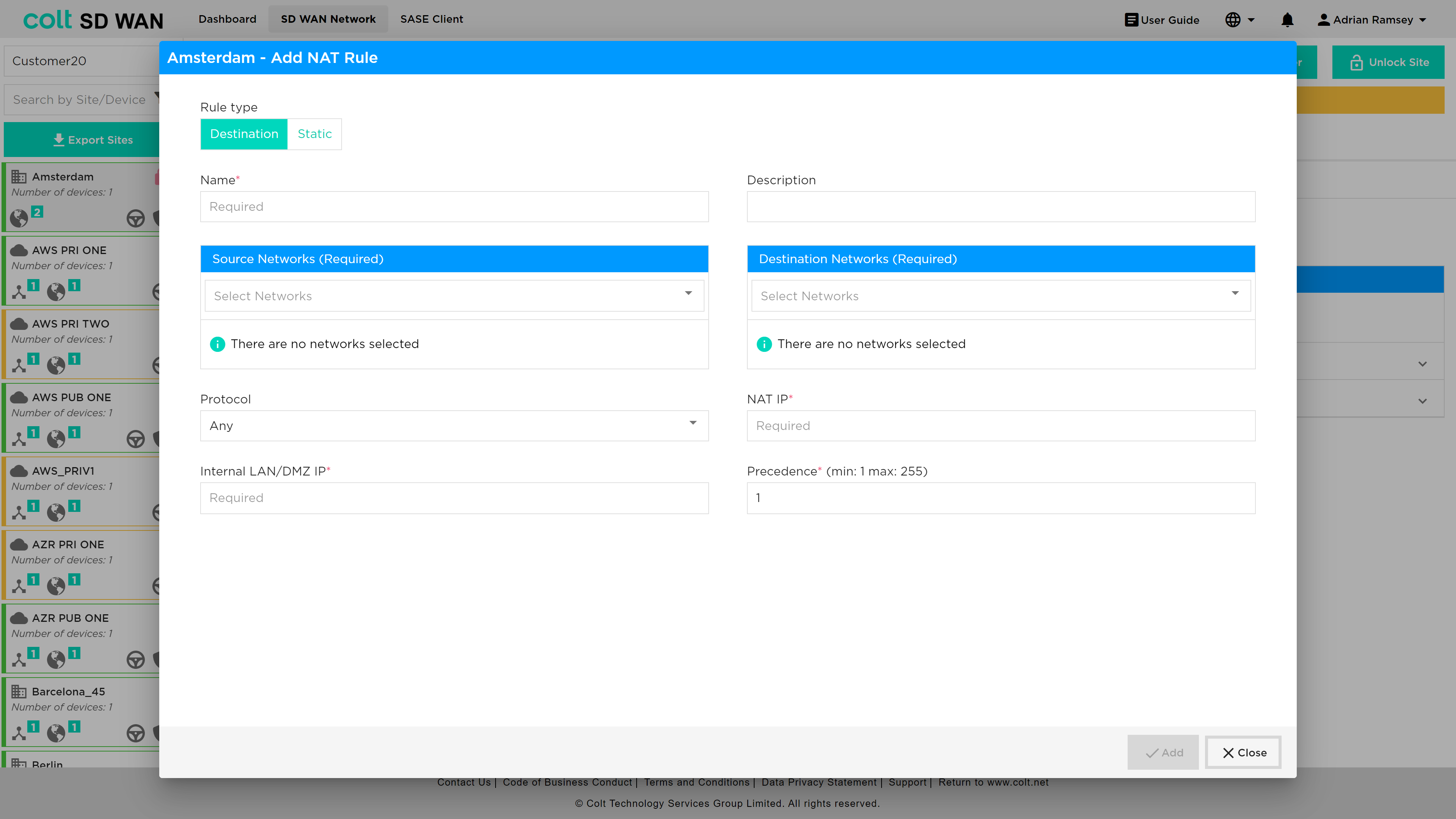
An example DNAT configuration is shown below.
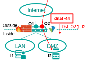
Inbound 1:1 Address Mapping
Inbound = Outside to Inside
Outbound = Inside to Outside
-
Map Inbound sessions from an outside destination IP (O2) to an inside IP (I2)
-
Uses Inbound dnat-44 Translation
-
External IP (O2) can be
-
Separate IP from WAN subnet (reachable via proxy ARP)
-
IP from separate NAT Pool (reachable via external route towards CPE WAN)
-
Outbound sessions still use NAPT-44 translation Use case:
-
Equipment in Customer DMZ that requires fixed external IP for inbound communication
-
e.g. VPN Gateway (server), Server that requires range of ports to be accessible externally
Iteration 2 adds the option for Static 1:1 NAT i.e. bi-directional mapping between an external IP and an internal IP in the DMZ or LAN. This used to allow traffic to and from the Internet towards a specific host in the DMZ or LAN using a fixed external IP
The basic-nat-44 translation type supports bi-directional 1:1 static NAT. Currently out of scope for static NAT are as follows:
-
Dual CPE with dual Internet
-
LAN-DMZ address translations
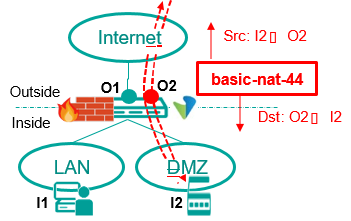
Inbound = Outside to Inside
Outbound = Inside to Outside
Both-ways 1:1 Address Mapping (Static NAT)
-
Map inside IP (I2) to a fixed outside IP (O2) for inbound and outbound sessions
-
Uses Inbound basic-nat-44 Translation ▪External IP (O2) can be
-
Separate IP from WAN subnet (reachable via proxy ARP)
-
IP from separate NAT Pool (reachable via external route towards CPE WAN) Use case:
-
Equipment in Customer DMZ that requires fixed external IP + outbound source port preserved and/or have issues with NAT traversal
-
e.g. IP-PBX, SBC, VPN Gateway (client + server).
An example screen shot for the static NAT configuration is shown below.