Policy Management
| Policy management provides multiple types of service that can be managed: Traffic Steering for SD WAN, Internet and SaaS applications, Central and Local Internet Breakout, Dedicated Gateway, Quality of Service (QoS) and Traffic Optimization. These are separate services managed via the same portal page. |
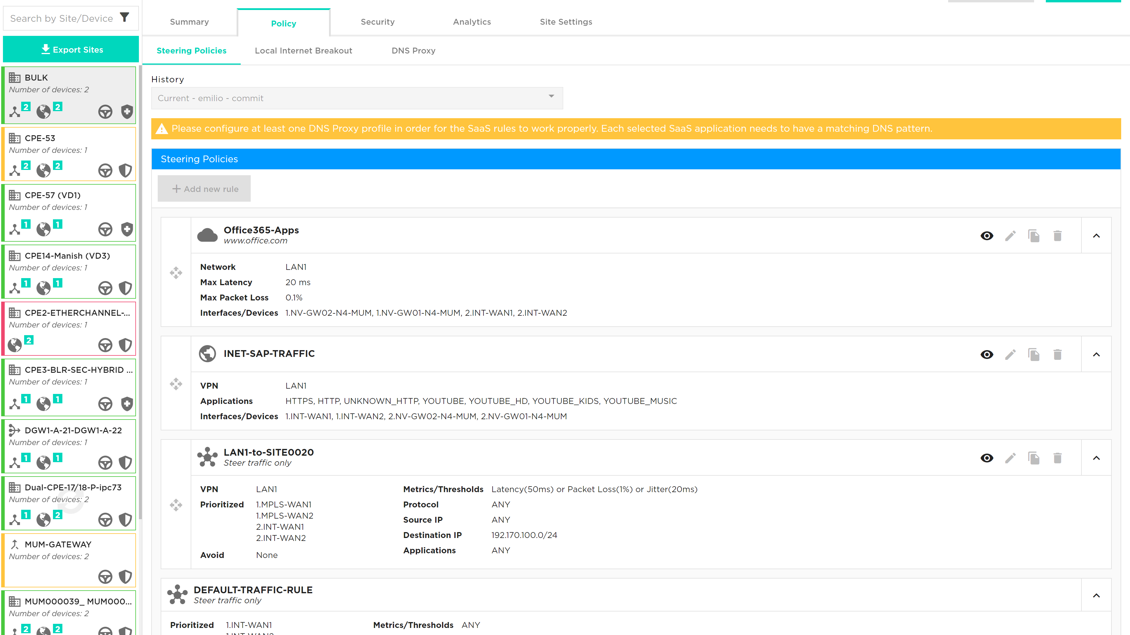
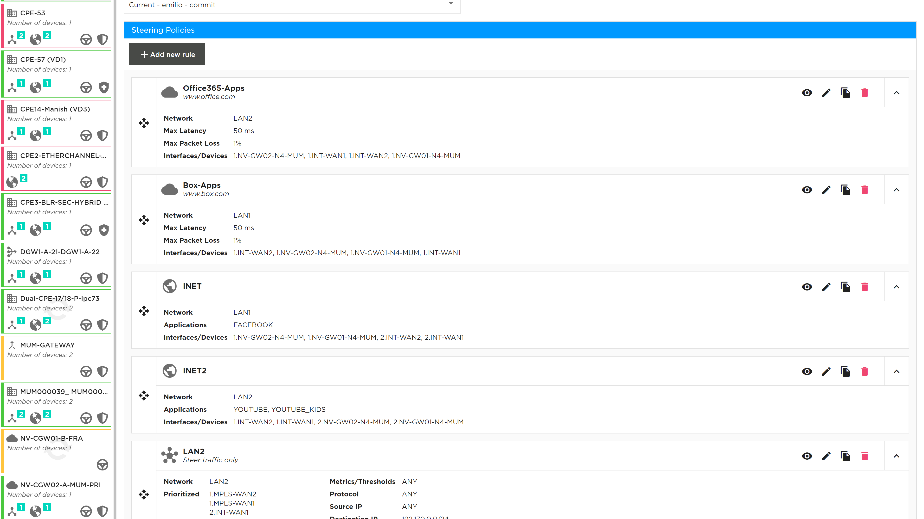
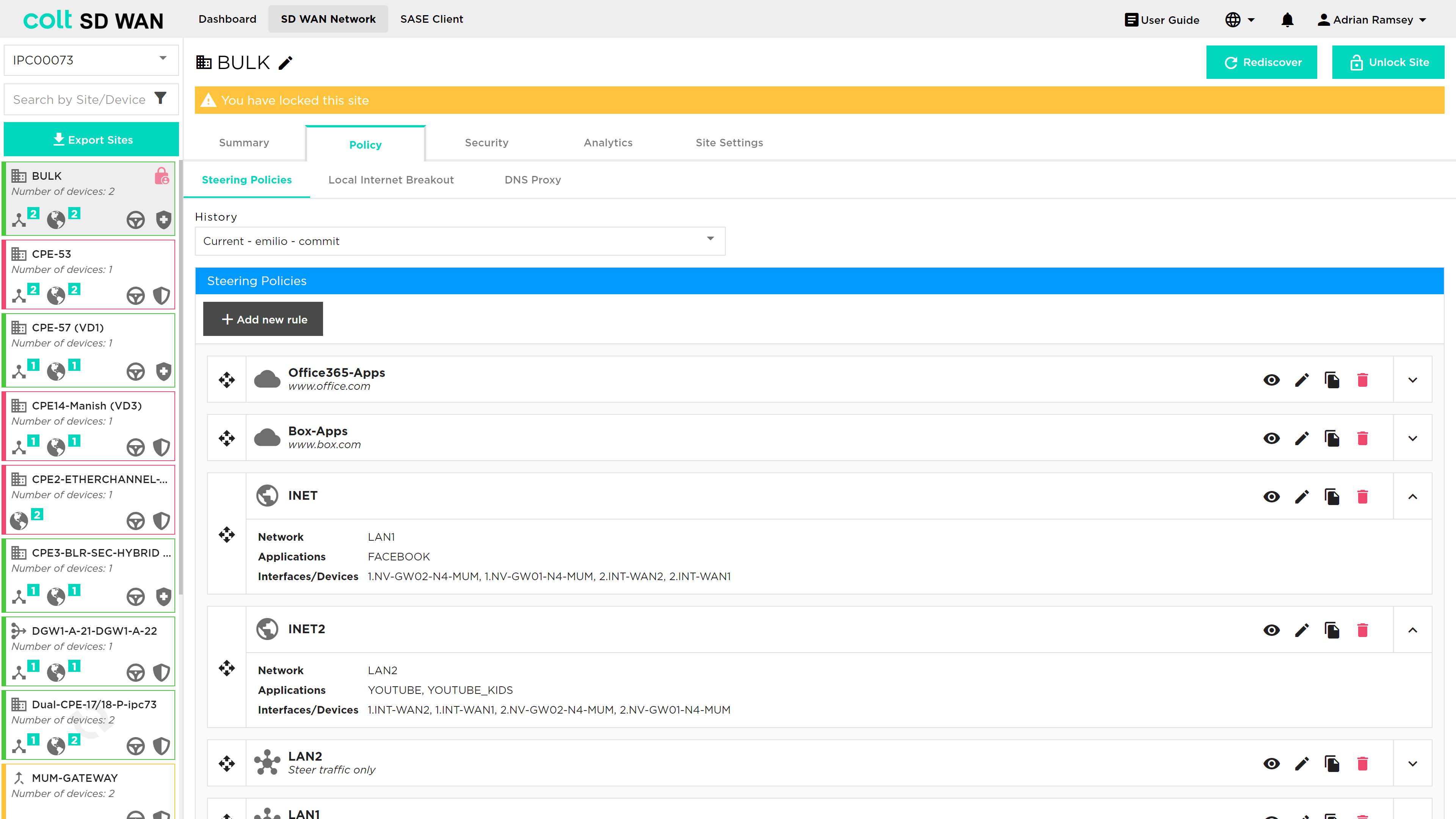
This page shows the list of traffic routing/forwarding policies; policies can be created, viewed, added, edited or deleted by portal users with the appropriate access permissions. Each of the existing policies show the interface order priority and SLA match criteria used to trigger traffic steering. On violation of any single metric traffic is steered to the next interface in the priority list.

While most policy properties can be edited, some features are disabled and need a specific service request – see below for details:
-
Metrics: Available metrics are Latency (milliseconds), Jitter (milliseconds), packet loss (%), Transmit Utilization (%), Receive utilization (%) and MOS score (0-5).
-
Threshold, as shown under metric, is the level at which traffic for that application will switch to the secondary link.
-
Primary Interface is the interface that application will use until a threshold is exceeded or there is a failure on the link
-
Secondary Interface is the failover from the primary interface when a threshold is exceeded
-
Policies were provided when the service was ordered. If there are no policies traffic will be load balanced across the links.
| Existing policies can be viewed but not edited, likewise new policies can’t be added until the “Edit Site” button has been selected to unlock the site. |
The Policy management tab allows source and destination IP/port combinations plus application level steering policies. The application signatures are provided by Versa using the SPACK process which automatically updates the application list.
The default behaviour of traffic routing is to load share across all available interfaces. The steering policy provides a default rule to ensure that traffic can be directed to avoid LTE interfaces and make use of the MPLS and Internet connections using the default rule.
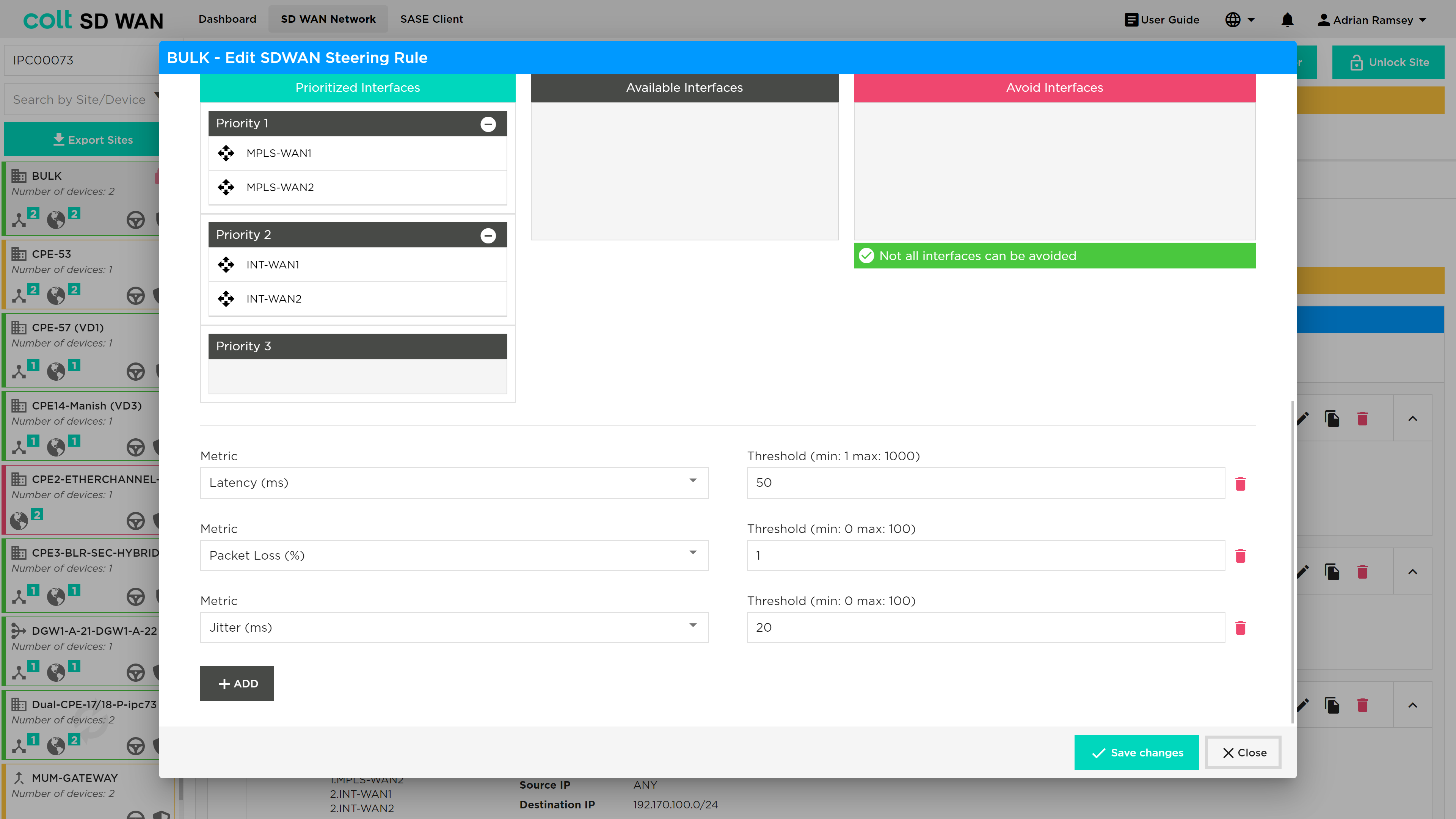
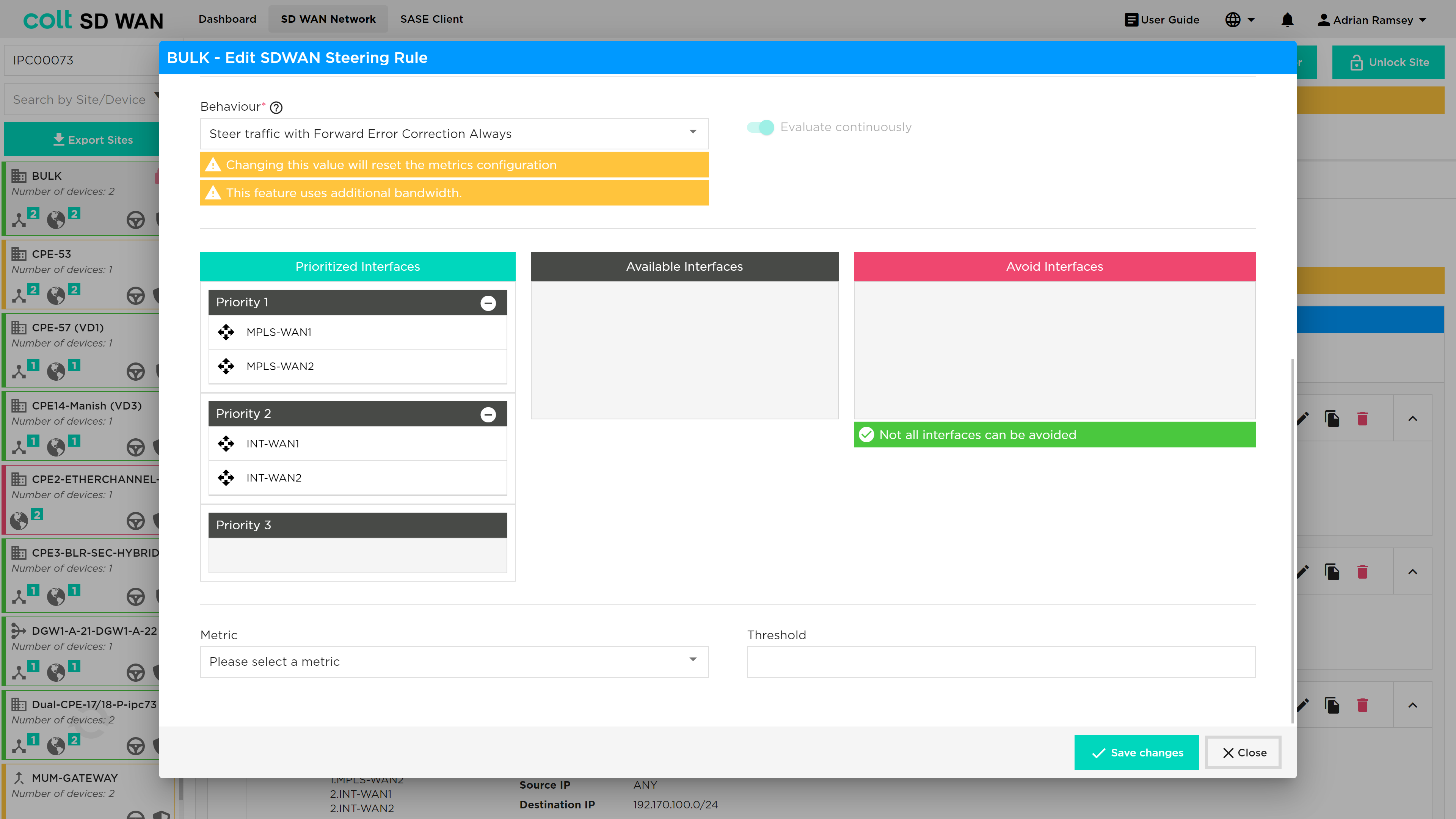
Multi WAN links introduces the option for an SD WAN Portal user to select the number and priority of each WAN interface they want to use or set to avoid when creating traffic steering rule. The screen shot below illustrates the new options.
Single or Dual CPE with Multiple WAN Links can also have default steering rules that allow Multiple uplinks of the same transport domain to be grouped and combined. For example, Dual Hybrid could have a default rule that allowed 2 MPLS links to load balance traffic. This allows for the example below priority 2 links to be used for traffic steering rules.
The traffic steering policies allow traffic to override the default traffic load sharing behaviour by routing based on:
-
Interface priority list
-
Protocol
-
IP and Port
-
Application
Traffic Steering Only
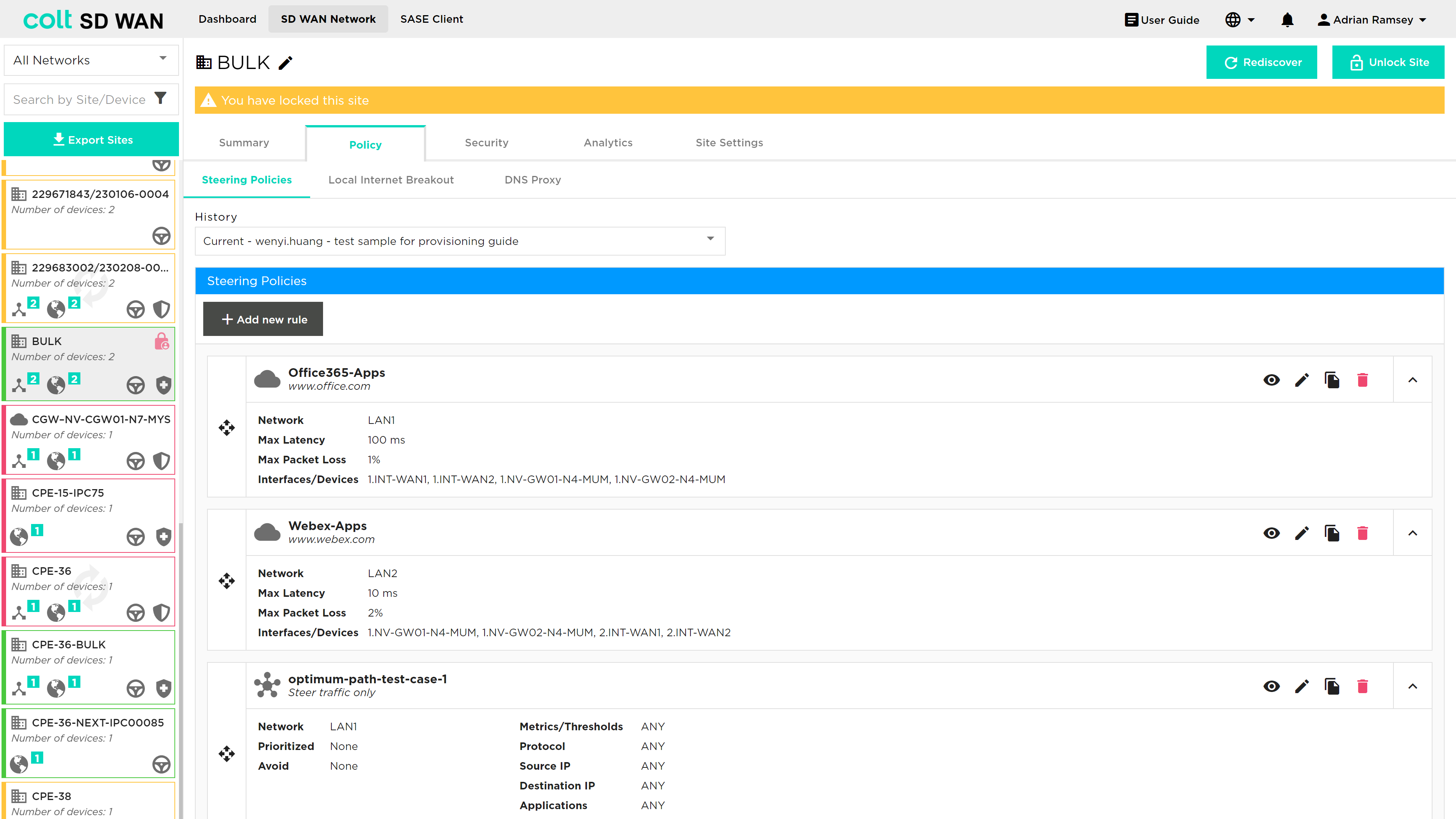
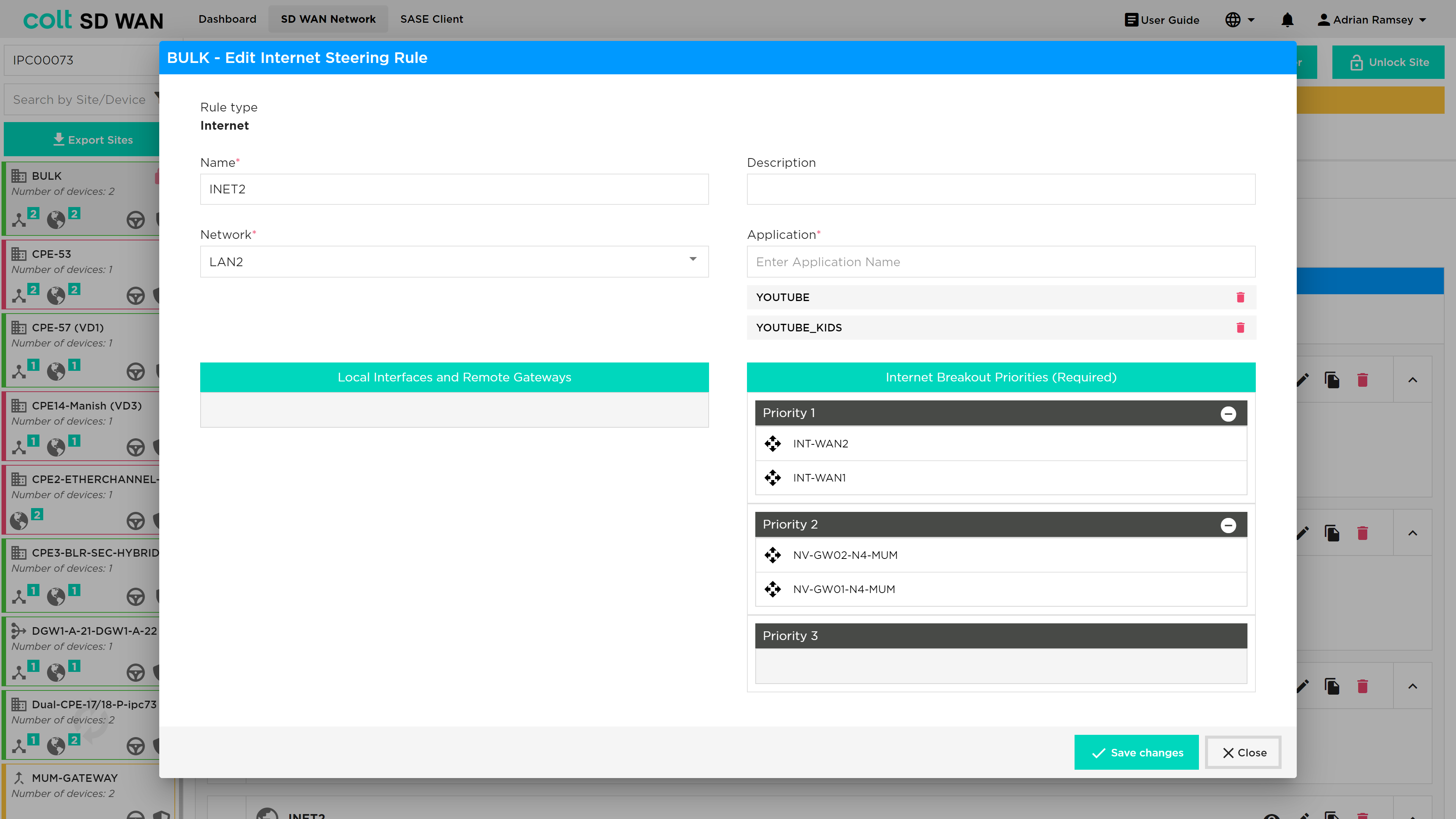
To edit the parameters, select an existing steering policy and the details will become visible with the options to edit or duplicate the policy. Note to enable editing of rules a user must first use the “Edit Site” button to lock the site from being changed by other users.
If you select edit, a new window will appear to allow the parameters selected for the policy to be edited.
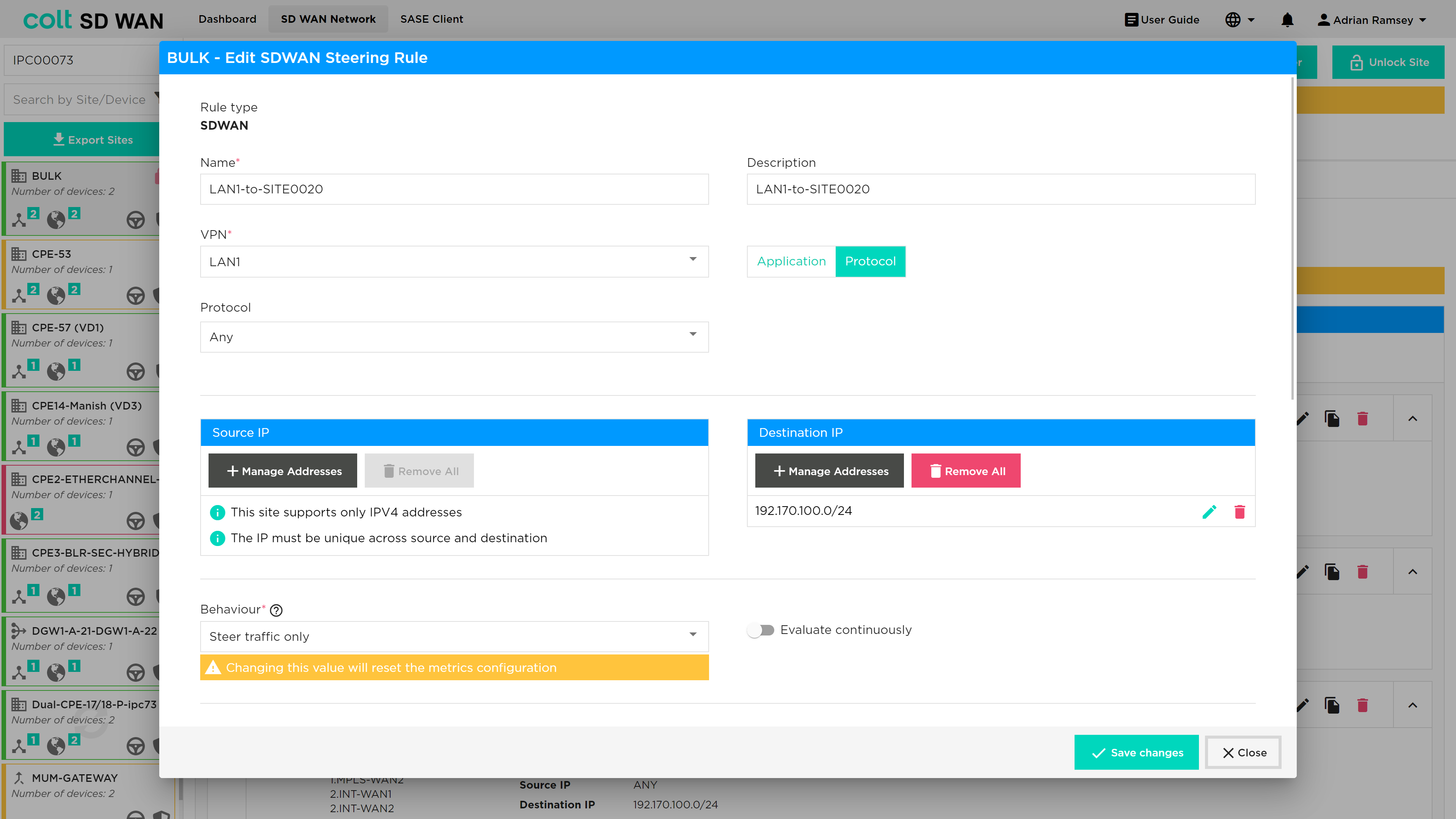
All Source and Destination IP fields can now be entered as a list of IPs, they don’t need to be added one by one. This changes what applied to all the Source IP and Destination IP fields in through the portal
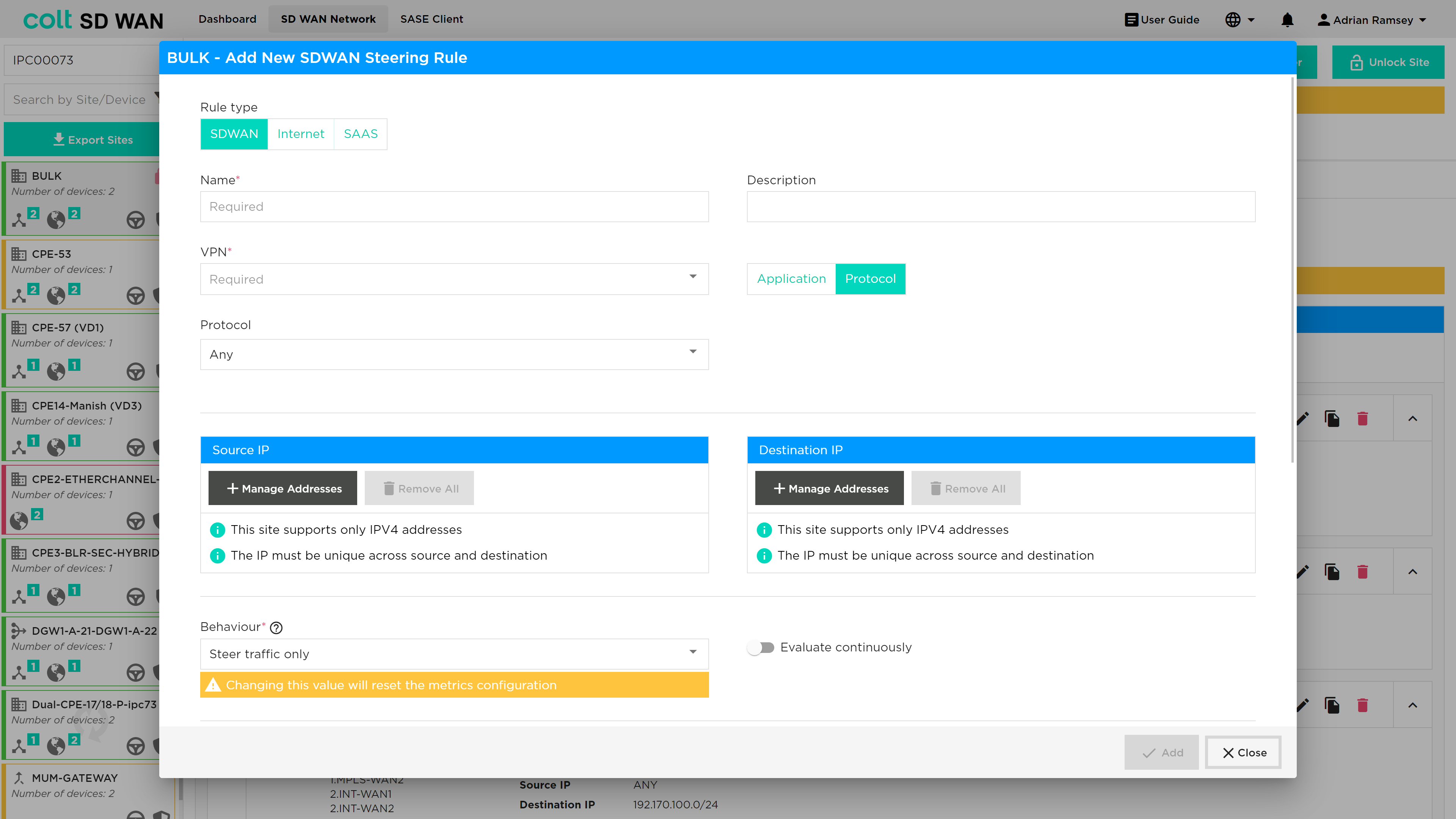
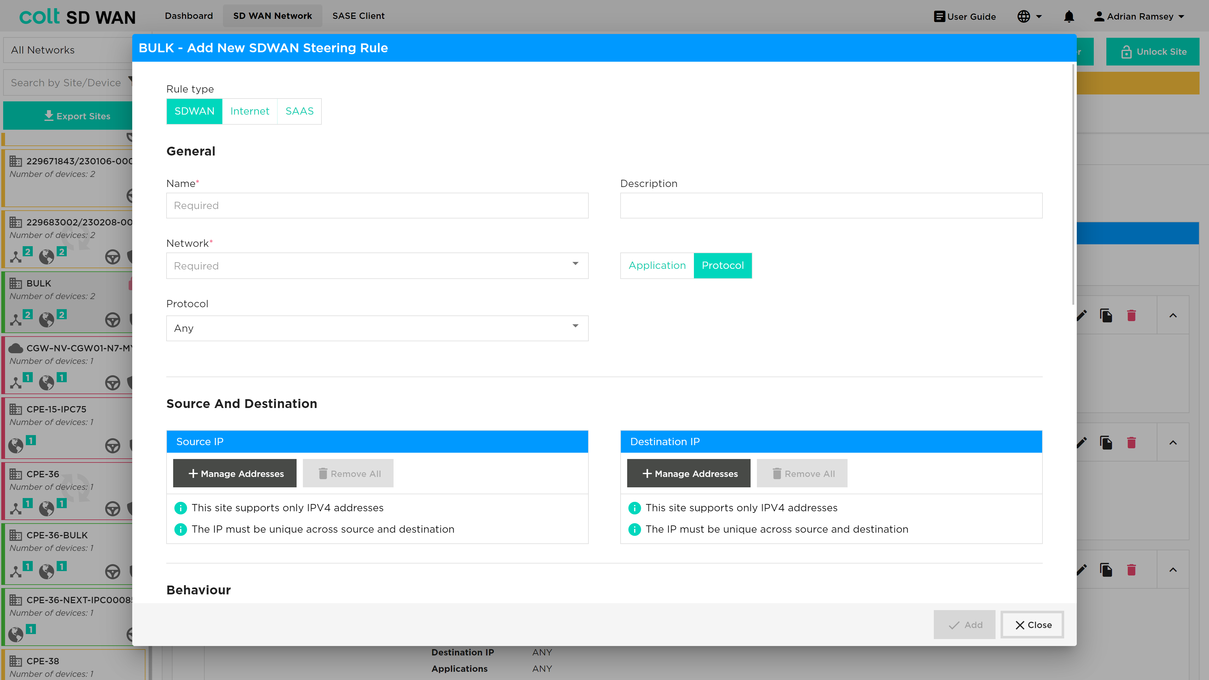
New traffic steering rules can be created by selecting the ‘Add New Policy Rule’ button on the top left of the Policy page which will open the screen as above when you edit pre-existing rules. The create policy allows the creation of traffic steering rules of type:
-
Name
-
VPN – drop down list of VPN labels or friendly names
-
Description – user defined description to label each policy
-
Protocol – Applied to source and destination (IP and ports)
-
Protocol list – Limited list and once selected the Port number boxes will become available to configure
-
Application – Pre-defined lists of applications which can be selected by search or scroll. Applied to all or by source and destination (IP and ports)
-
Interface Priority list
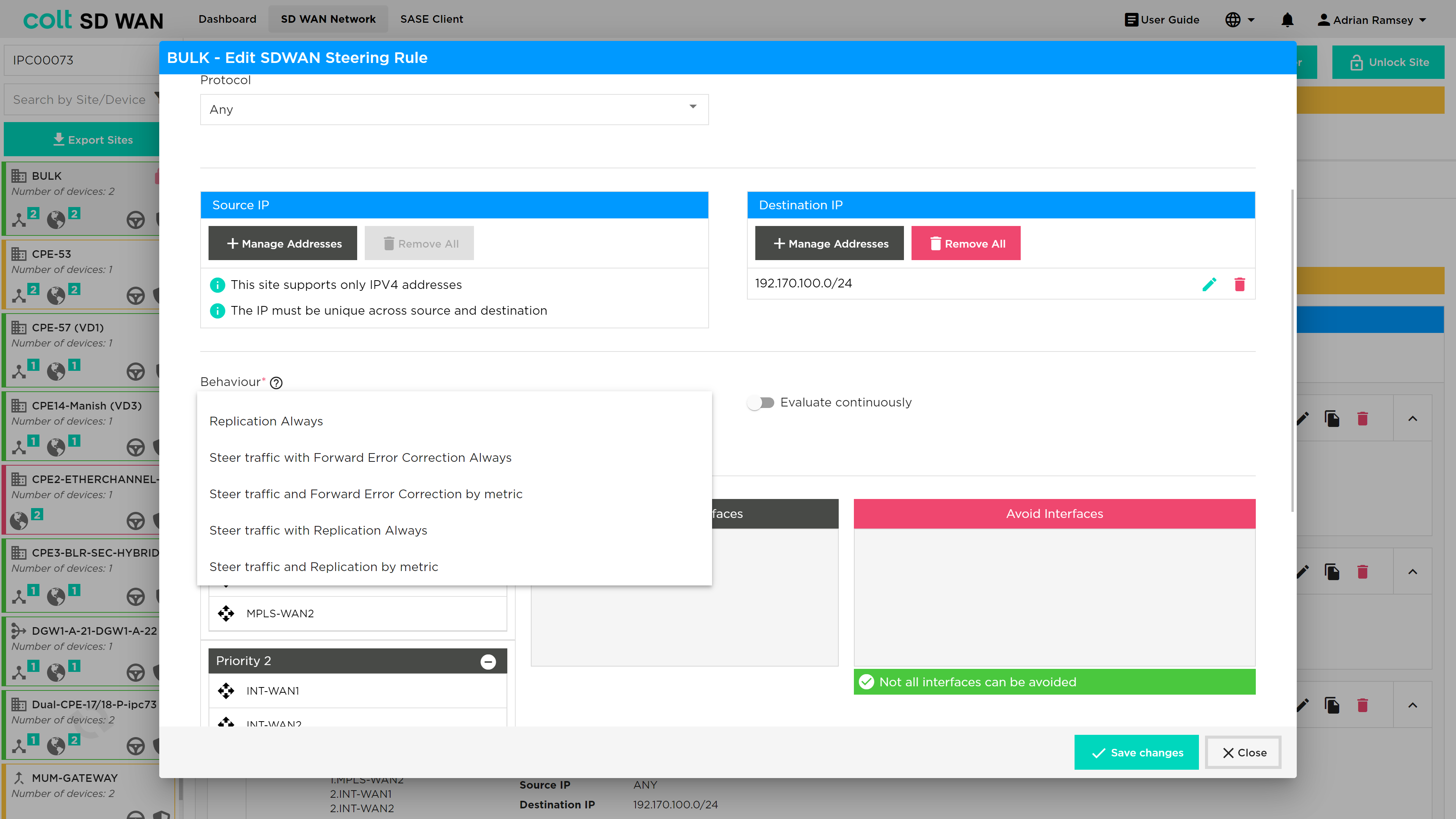
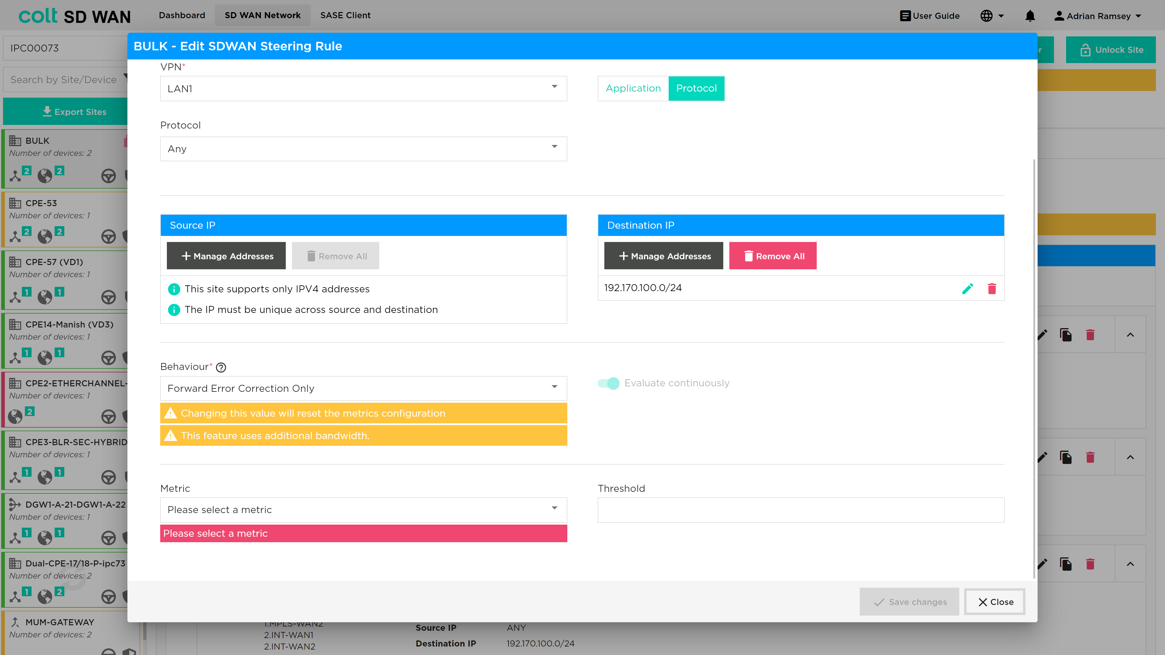
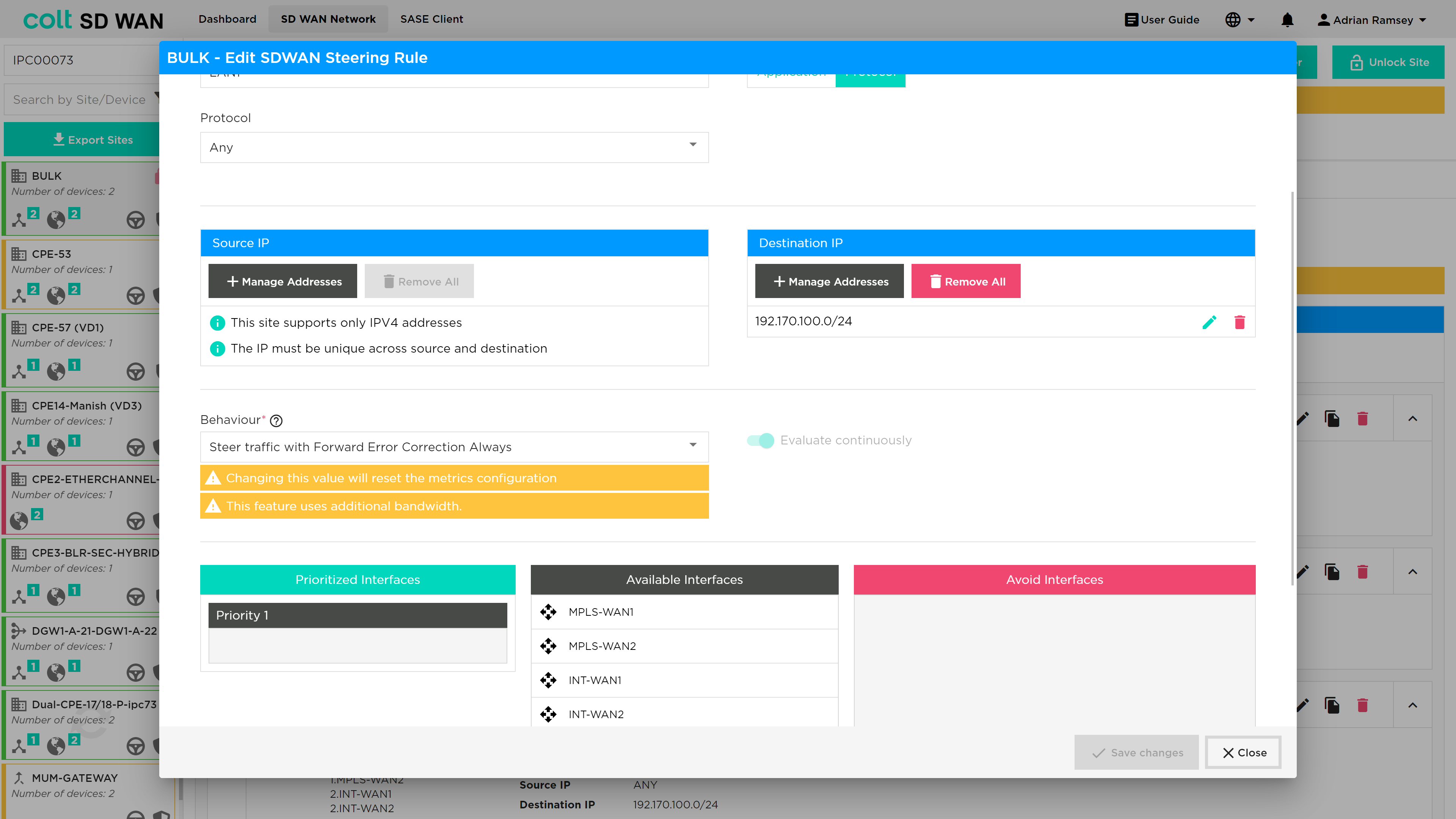
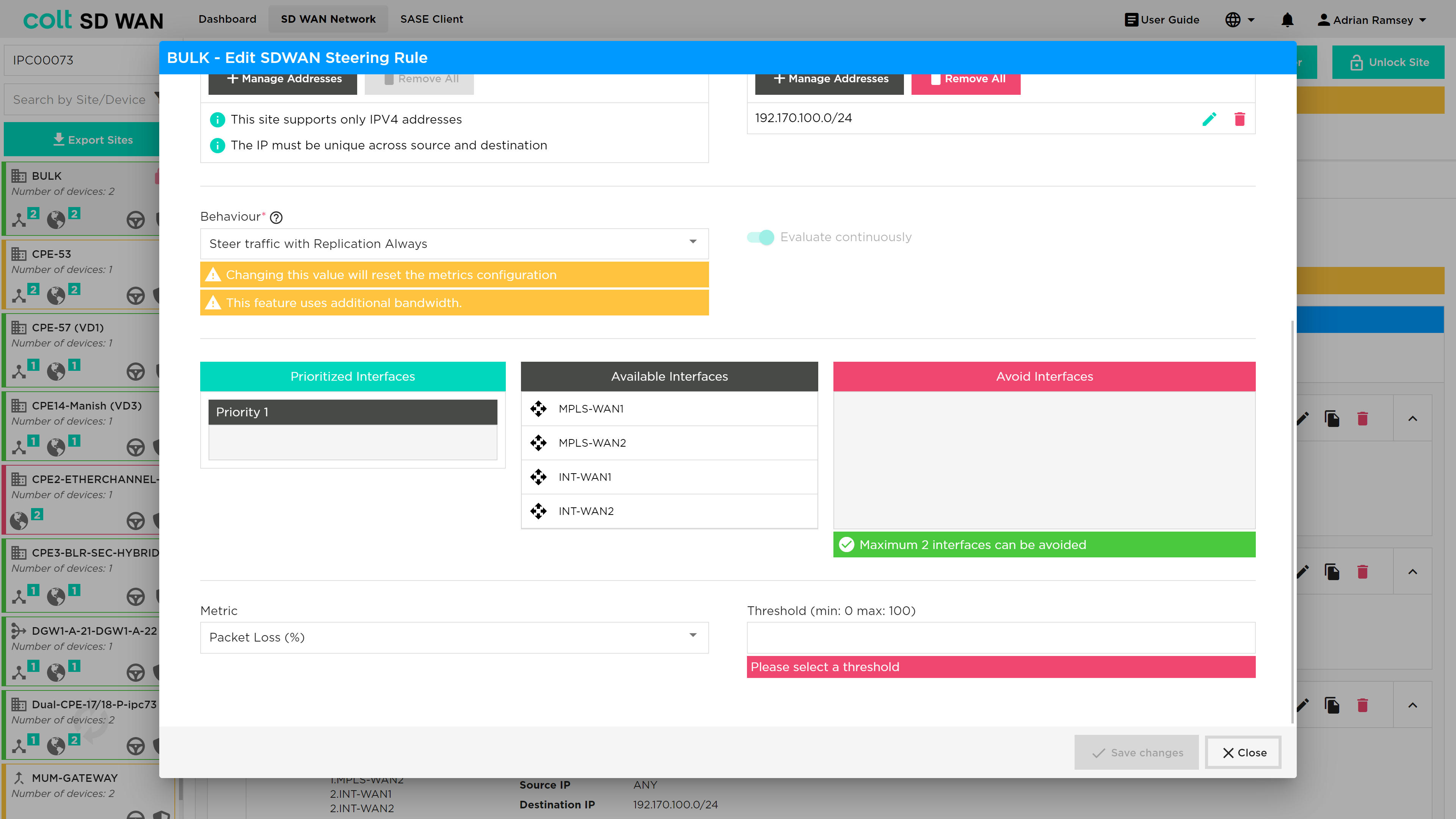
Traffic steering matches an IP address from a VPN to an application or IP protocol/port combination. It then allows that specific traffic to be routed in a priority interface list, overriding the default traffic load balancing behaviour of the SD WAN service. Traffic steering is applied to sites with more than one available WAN link. The metrics provide thresholds that trigger traffic to be steered to the next WAN link in the priority list. There is an option to ‘Avoid’ certain WAN links for specific traffic steering rules.
To create rules, you need as a minimum the following fields:
-
Name – Representative text or number, no spaces
-
VPN – A source interface for the traffic LAN or DMZ
-
Protocol or Application selected
-
Interface 1 and Interface 2 as priority list
-
Metric – At least one metric type to specify the SLA threshold to steer traffic
If Protocol ‘Any’ is selected and no IP address or port numbers specified, all traffic from that VPN will be steered using the Interface priority list and metrics
Multiple source and destination IP address can be created to match in a single steering rule by using the ‘add +’ buttons.
Local Internet Breakout (LIB) traffic is routed based on IP route options defined outside of the scope of the SD WAN Portal.
Multiple metrics can be applied to each new rule be adding a Metric using Add option underneath each metric.
| Navigate to Policy and click on ‘Add new Policy’ button, click on Metric dropdown, make sure the ‘MOS score’ option is enabled for VoIP enabled devices. |
| VoIP Traffic is subject to the default per flow load-balancing inherent to the SD WAN solution so VoIP calls (SIP and RTP flows) to and from sites with multiple transports will be load-balanced across the available paths which might lead to inconsistency in call quality. To override this behaviour the customer needs to manually define traffic steering policies first for their sites that are using VoIP and secondly in the Gateway to ensure symmetric behaviour. This can be done by customers via the Colt Self Service Portal and it´s advisable to use the MPLS transport whenever available. |
The ‘Evaluate Continuously’ option will be visible for all types of devices for which policy is enabled. The option allows the SD WAN path SLA or metric to be monitored and tested periodically if Evaluate Continuously is not selected (the default setting) or continuously if it is selected. This is recommended for VoIP or applications with media codecs.
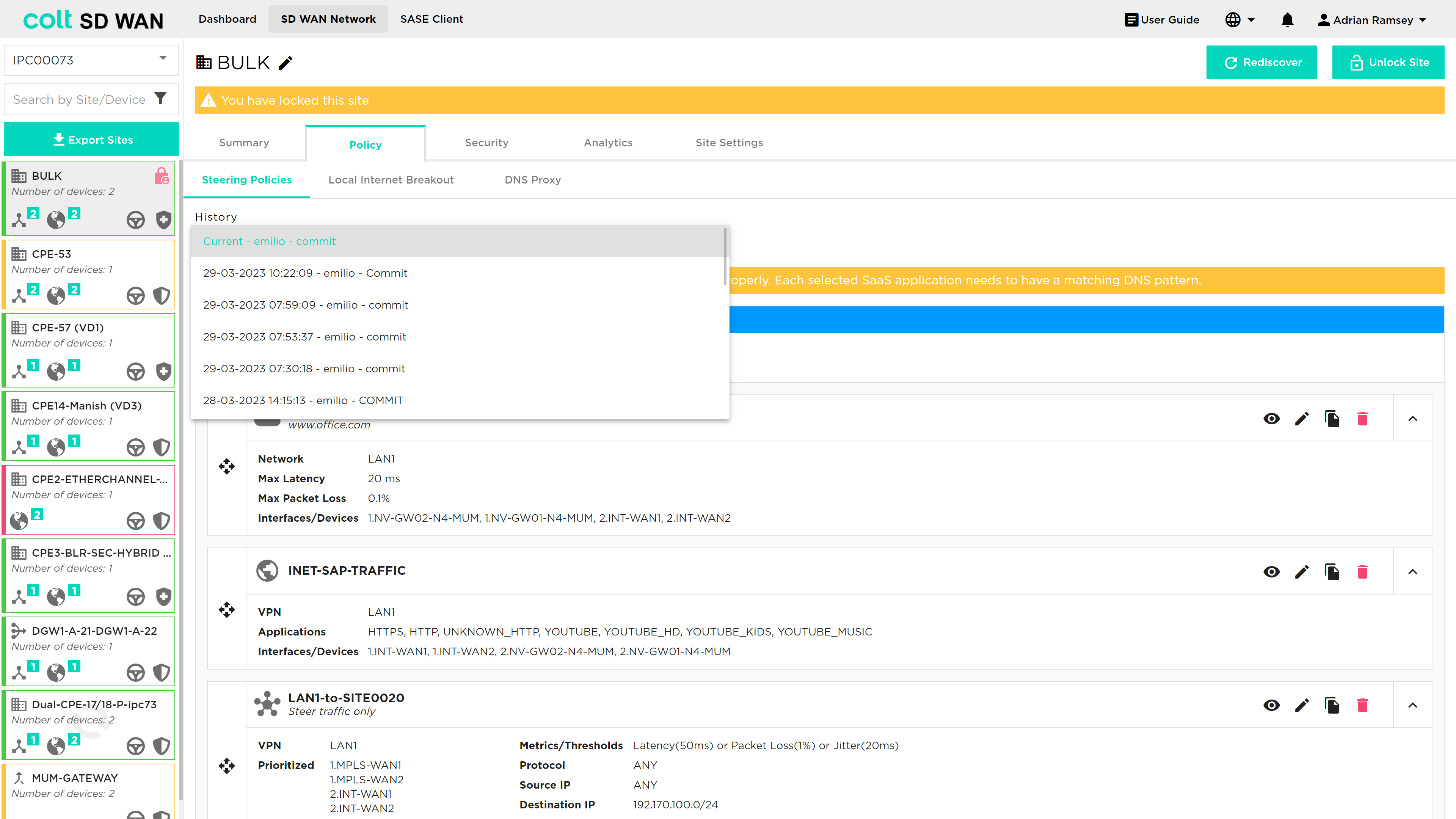
You can view and roll back past changes to policy configurations by selecting history button to view the log of policy changes. Selecting a policy log will display the list of steering policies captured before the policy as changed. These policies can be enabled by selecting the save changes button.
Optimum Path Selection
Optimum Path Selection is a non-chargeable feature that provides the best path selection between all available paths when a 10% variance in performance is reached. This is a variation to the standard SD WAN traffic Steering rules where the path selection for traffic is based on circuit priorities and/or SLA thresholds instead of performance. Optimum Path Selection can steer traffic automatically based one or several metric(s), for example lowest latency, lowest packet loss or lowest delay variation. Dynamic path selection can be selected from the same page in the portal as standard SD WAN steering rules.
Configuring of Optimum Path Selection has a number of dependencies:
-
More than one WAN Transport link enabled
-
Selection of at least one of the metrics from the SLA Profile: Low latency, Low packet loss and Low jitter selectable using the portal
-
The same SLA profile that today is created and associated with the policy when the SLA metrics are configured in the portal is needed for Optimum Path Selection
To select Optimum Path Selection, the user navigates to the Steering Policies page, found under the Policy tab as shown below:
Once the user locks the site to enable editing, then a new rule can be added by pressing the '+ Add new rule' button. The user can then select 'SDWAN' at the top of the steering window as shown below:
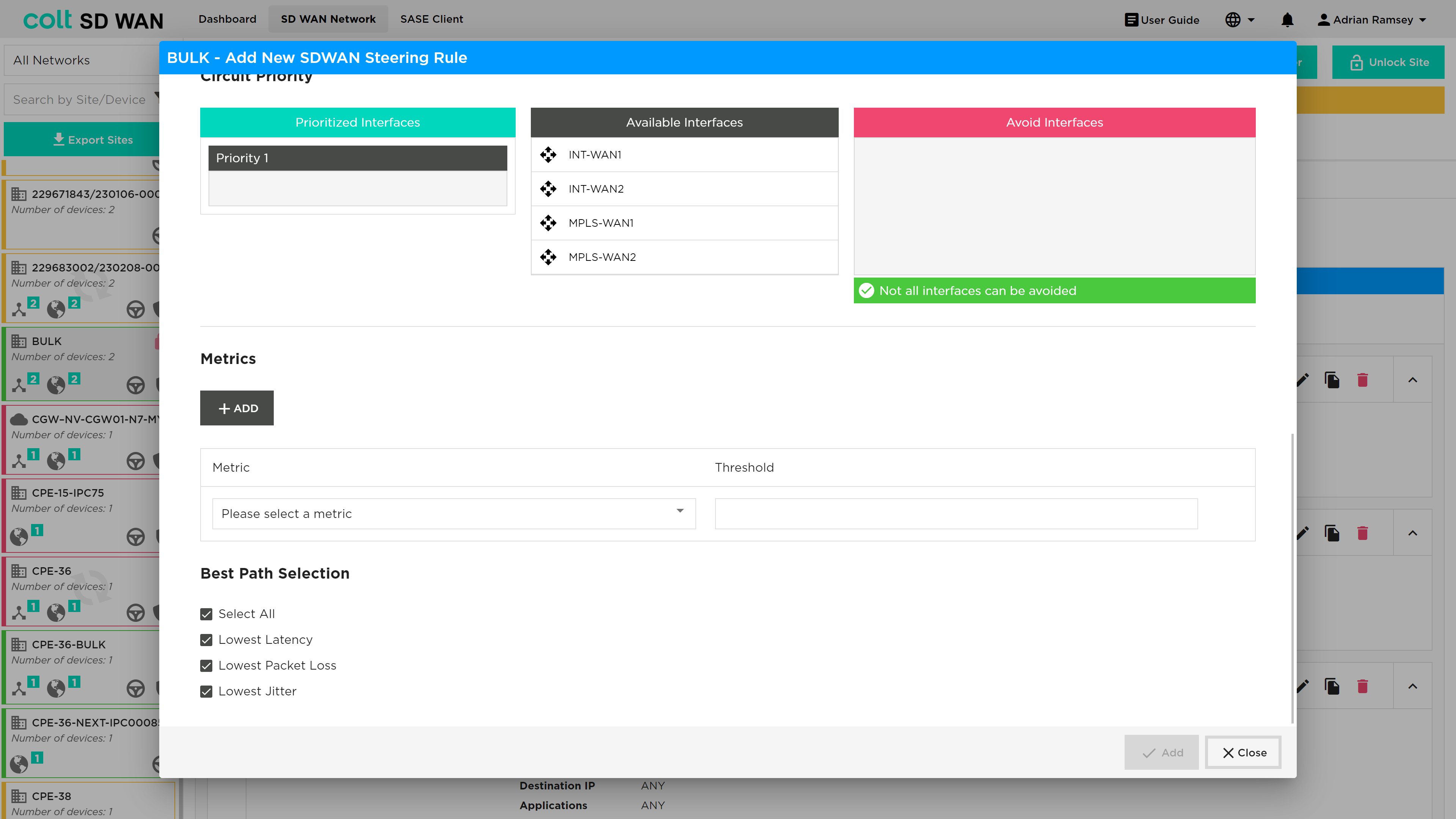
At the bottom of the 'Add New SDWAN Steering Rule' window the user is able to set the Best Path selection as shown below:
There are a variety of combination possibilities best path selections and using this capability with or without more deterministic steering rules. We will explain this below including the main example use cases, starting with the detail of the Dynamic Path Selection configuration parameters.
Explanation of new configuration parameters:
-
Best Path Selection (Optional, single choice): Button for activating the behaviour of Best Path Selection. If selected then the three lower metrics fields will appear on the panel as selected by default.
-
New three Metrics (Mandatory, Multiple choice): o Lowest Latency (Optional): To configure the best path based on the lowest latency. No Threshold value can be configured. o Lowest Packet Loss (Optional): To configure the best path based on the lowest packet Loss. No Threshold value can be configured. o Lowest Jitter (Optional): To configure the best path based on the lowest Jitter. No Threshold value can be configured.
As mentioned, in addition to this functionality for traffic selection, existing options that we provide for SD WAN traffic Steering Rules are still available. These are:
-
Configuration of different circuit priorities
-
Configuration of SLA thresholds for several metrics: Latency (ms), Jitter (ms), Packet loss (%), Transmit/Receive Bandwidth utilization (%)
-
Continuous evaluation of the traffic sessions that provides the traffic switching between difference paths, when the used path is no longer SLA compliant or there is a better option with <10% of difference
For implementation of Optimum path selection there are 4 use cases:
USE CASE 1: Best Path Only (Simple Case)
-
Site Type: Single CPE with MPLS and Internet WAN
-
Policy Rule: Match Selected Traffic, Enable best path for one or more metrics, no circuit priorities, no SLA thresholds
-
Normal Behaviour: Best path used, or both if performance difference is <10%.
USE CASE 2: Best Path with circuit priorities
-
Site Type: Dual CPE with MPLS, Internet and LTE WAN
-
Policy Rule: Match Selected Traffic, Enable best path for one or more metrics, MPLS and Internet Priority 1, LTE Priority 2, no SLA thresholds
-
Normal Behaviour: Best path amongst MPLS and Internet circuit used (or both if performance difference is <10%). LTE is unused
-
Failure 1 - MPLS path down: Internet path Used. LTE is unused
-
Failure 2 - Internet path down: MPLS path used. LTE is unused
-
Failure 3 - Both Internet and MPLS down: LTE path used
USE CASE 3: Best Path with SLA thresholds
-
Site Type: Dual CPE with MPLS, Internet1 and Internet2 WAN
-
Policy Rule: Match Selected Traffic, Enable best path for one or more metrics, no circuit priorities, SLA thresholds set (e.g. 100ms latency, 80ms jitter, 5% packet loss)
-
Normal Behaviour: Best path amongst MPLS, Internet1 and Internet2 WAN used (or multiple best paths if performance difference is <10%)
-
Failure 1 - SLA on MPLS path only exceeds thresholds e.g. latency >100ms: best path amongst Internet 1 and Internet 2 used, or both if performance difference is <10%.
-
Failure 2 – MPLS path down: Best path amongst Internet 1 and Internet 2 used, or both if performance difference is <10%.
USE CASE 4: Best Path with circuit priorities and SLA thresholds
-
Site Type: Dual CPE with MPLS, Internet1 and Internet2 WAN
-
Policy Rule: Match Selected Traffic, Enable Best path for one or more metrics, MPLS Priority 1, Internet1 and Internet2 Priority 2, SLA thresholds set (e.g. 100ms latency, 80ms jitter, 5% packet loss)
-
Normal Behaviour: MPLS path used
-
Failure 1 – SLA on MPLS path exceeds thresholds e.g. latency >100ms: best path amongst Internet 1 and Internet 2 used, or both if performance difference is <10%.
-
Failure 2 – MPLS path down: Best path amongst Internet 1 and Internet 2 used, or both if performance difference is <10%.
Traffic Optimization
|
Traffic Optimization using FEC and Packet Replication requires a knowledge of the WAN Optimization. The inappropriate selection of these features can result in reduced performance of your SD WAN CPE and increased utilization of WAN links. Colt provides these services but does not provide a design recommendations or support decisions made by customers when using these features. FEC and Packet Replication policies apply to traffic originating on the LAN/DMZ and towards the SD WAN network only. |
Traffic optimization uses FEC (Forward Error Correction) and Packet Replication combined with the option for traffic steering of specific applications with and without metrics. Below are short descriptions of FEC and Packet Replication for background information.
Traffic optimization provides an ability to enable the following services with and without traffic steering:
-
Forward Error Correction
-
Packet Replication
The basic setting allows customers to do the following:
-
Set FEC and Packet replication to be always on
-
Enable FEC and Packet replication when a user defined Packet Loss threshold has been reached
-
Steer traffic with FEC and Packet replication from one link to another
-
Steer traffic with FEC and Packet replication from one link to another using the link priority list and packet loss metric
| When traffic steering and FEC/Packet replication is enabled, the order of action is that traffic steering will take priority. Then once traffic has been steered to the last WAN link in the priority order, traffic optimization will be enabled when packet loss is equal to the set threshold defined in that rule. |
A full list of the traffic steering and shaping combinations are shown in the Appendix under WAN Optimization rules.
Always enable FEC and Packet Replication:
Enable FEC or Packet Replication when the Packet Loss threshold has been reached:
Packet steering when FEC or Packet Replication is always on:
The Packet Loss metric allows you to set the % of packet loss by entering a specific value. This metric measures the percentage of lost packets in a network.
Traffic steering when FEC and Packet Replication is always on but no metric set:
Traffic steering also allows the option to ‘avoid’ interfaces in the priority list. This is used to ensure traffic does not utilize WAN connection that don’t have the characteristics or bandwidth to support the underlying services.
Local Internet Breakout
| This feature can only be used after respective firewall rules have been added from the Security tab of the branch device. |
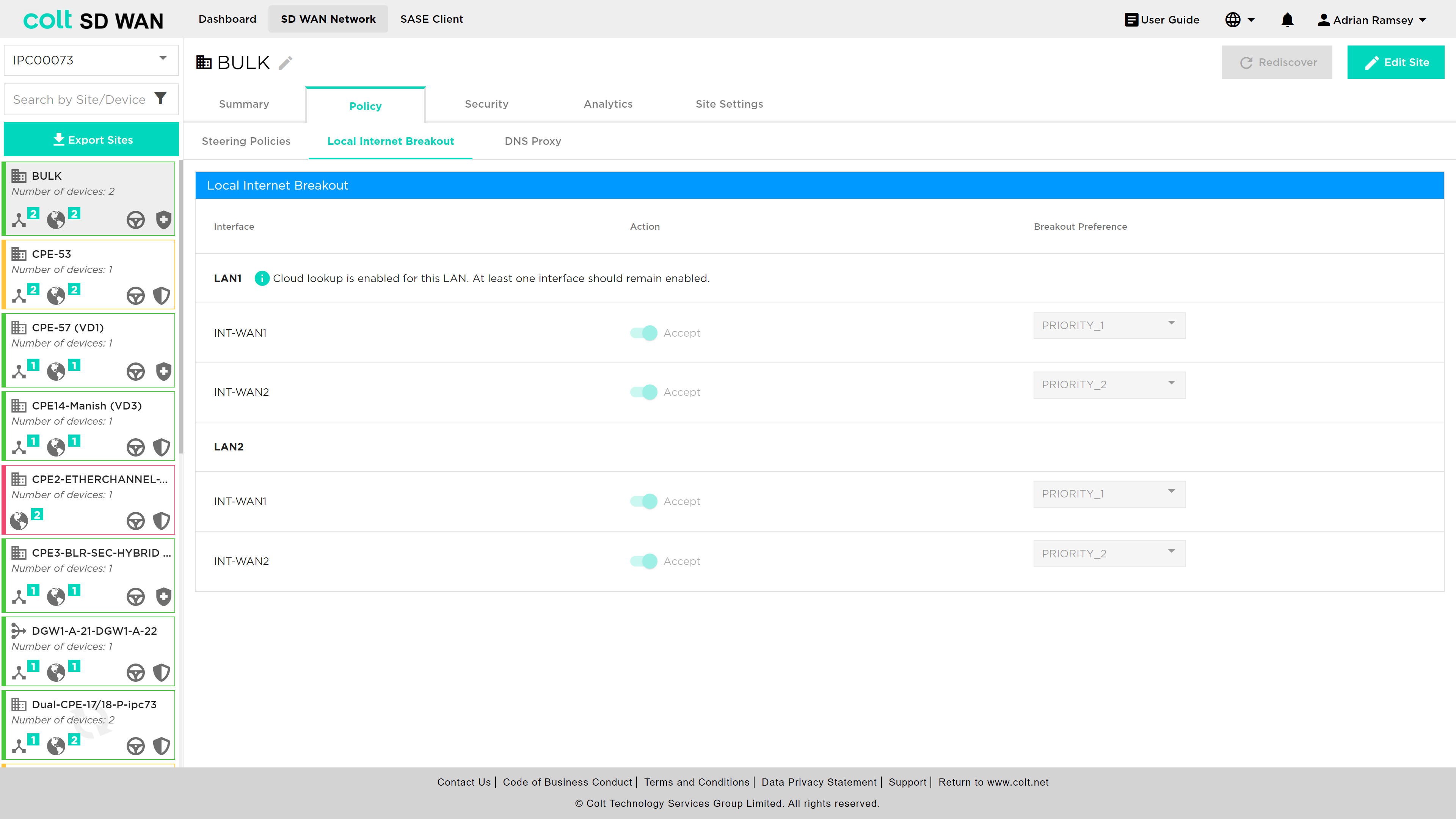
As mentioned above, local internet breakout can be specified for each VRF/VPN. The default configuration for sites with multiple internet WAN connections is load sharing, where all local interfaces are set to the same priority. The list of Local WAN interfaces is provisioned at the time the site is implemented. It is possible to disable specific interfaces or modify the priority order for outbound traffic utilization. The process for chaning can be shown below.
| Customers with URL Filtering must maintain at least one active WAN connection to ensure cloud lookups can be made from that site. |
Central Internet Breakout
| This feature can only be used after respective firewall rules have been added from the Security tab of the gateway device. |
In addition to local Internet breakout, the Customer will have the option of selecting central internet breakout. There are 3 options for Customer dedicated Central Internet gateway:
-
Customer hosted (SD WAN site) Internet gateway
-
Colt hosted Internet gateway (no SDWAN hub or MPLS NNI)
-
Dedicated SD WAN Gateway (SD WAN Hub/MPLS NNI and Internet gateway)
-
Branch SD WAN Gateway (SD WAN Hub/MPLS NNI and Internet gateway)
For SDWAN sites enabled with Local Internet Breakout, Internet traffic will be routed over local Internet WAN uplink. In case of LIB failure, traffic will be routed route over central internet gateway.
In case of Internet link failure, Internet traffic from SDWAN branch sites to Customer Internet gateway will be over SDWAN overlay on MPLS from branch to gateway for hybrid sites.
For MPLS only sites, Internet will be accessible through Internet gateway sites.
A customer will have Central Internet Breakout configured at a network level as opposed to on a site level. With Central Internet Breakout the customer no longer requires any particular site to have a local Internet connection to break out to the Internet. Steering is configured on the Internet Traffic Steering tab as shown below.
Internet Traffic Steering
| Where previously SD WAN Steering rules took precedence over Internet Steering rules, this is no longer the case and the order of processing will be as the user selects and is displayed in the site summary of all rules. |
Internet Break out options have been introduced to allow SDWAN Portal users to do the following on a per site bases:
-
Enable Local Internet Breakout for outbound (LAN to Internet)
-
Enable Central Internet Breakout for outbound (LAN to Internet)
-
For each elect additional Internet Breakout gateways for internet outbound traffic
-
Create application policies to steer internet traffic to priority list of Internet or Internet gateways
Internet Breakout is provided through the Internet WAN interfaces. By default, the customer will have at least one Internet interface enabled and set with a priority of 1 for local internet services, including cloud lookup, as shown below:
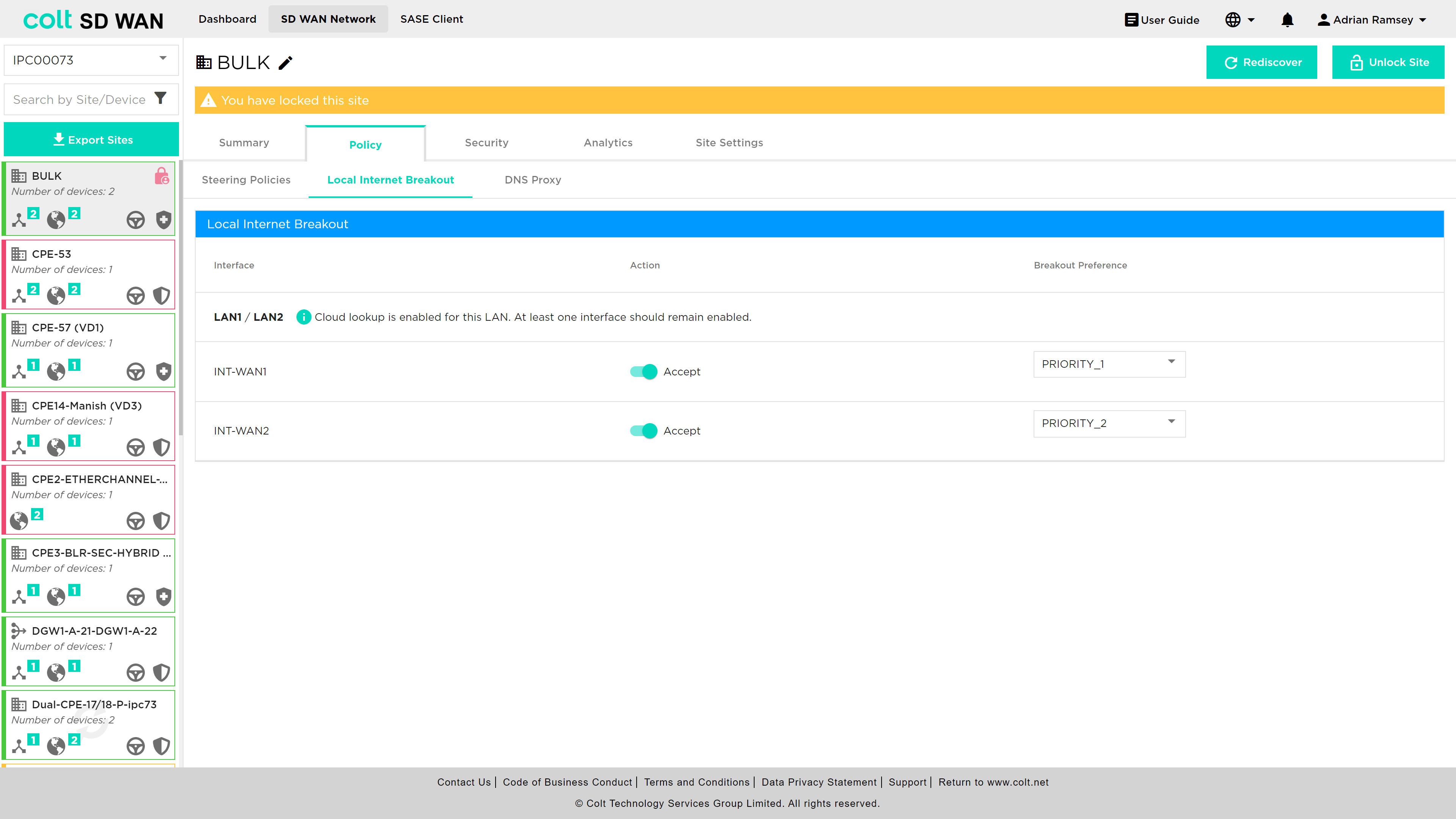
By default those customers who have multiple Internet WAN connections on the same site will have all enabled for local internet in Active/Active configuration for outbound traffic. A customer can choose to change to a ordered list of breakouts by changing the priority assigned to each.
Internet Traffic Steering provides the ability to view, edit, add and delete application based traffic steering rules per site. New rules can be added as shown below:
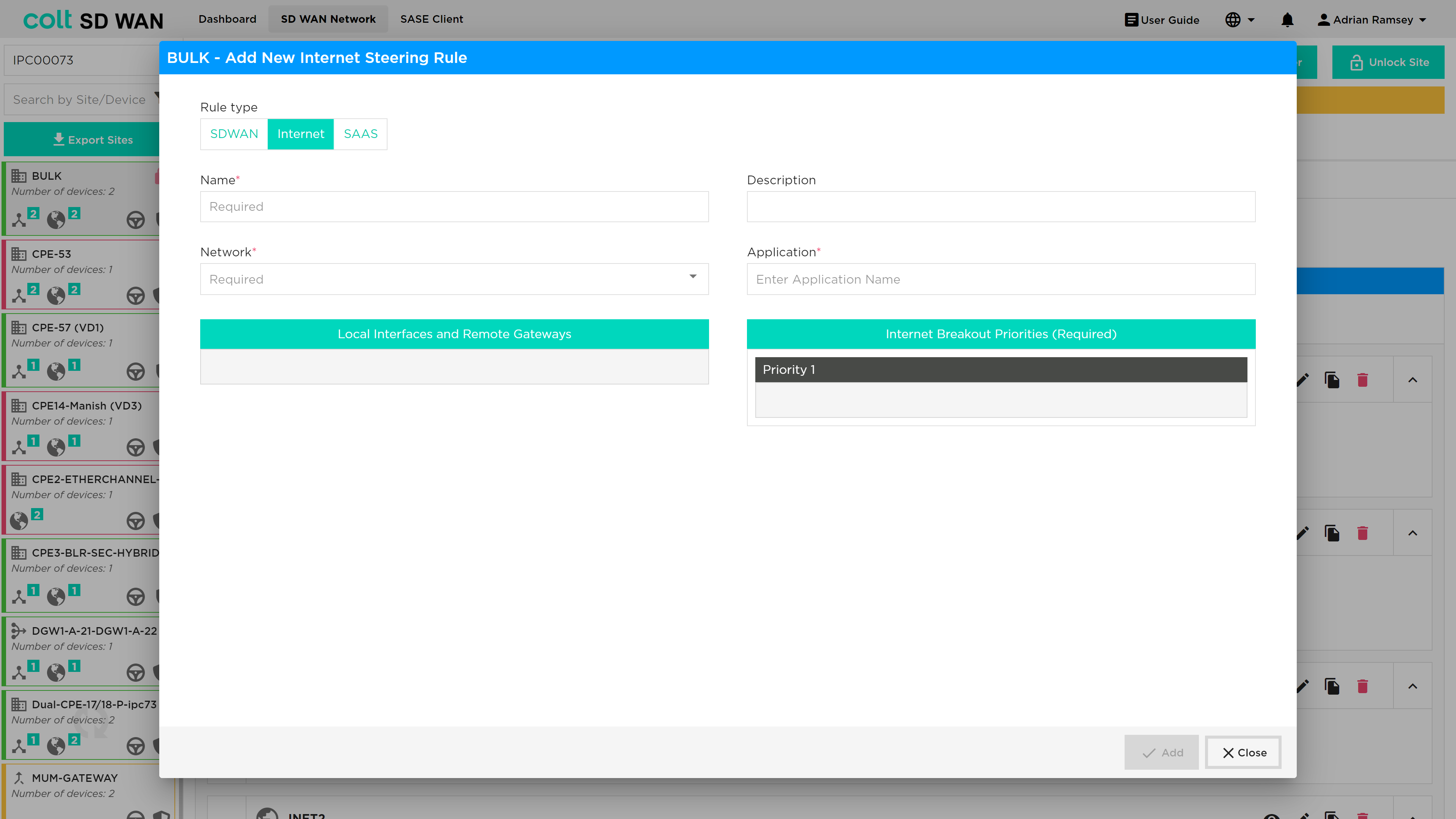
The options allow selection of the application by VPN and the creation of a ordered priority list for internet breakout traffic only. The list of available outbound interfaces will be Central Internet Breakout Gateway or local internet interface at that site.
| Inbound Internet traffic will be managed per interface, i.e. the primary link will be used or if DNS or specific applications use an IP address assigned to a subnet on another Internet WAN link then specific DNAT/SNAT policies and FW rules need to be created. These can be created per device, which includes the Branch and Central Internet Gateways. |
A list of gateways that are linked to each branch site can be viewed from the Device page.
See below the dialogue box for adding a new internet traffic steering rule:
List view of internet traffic steering rules:
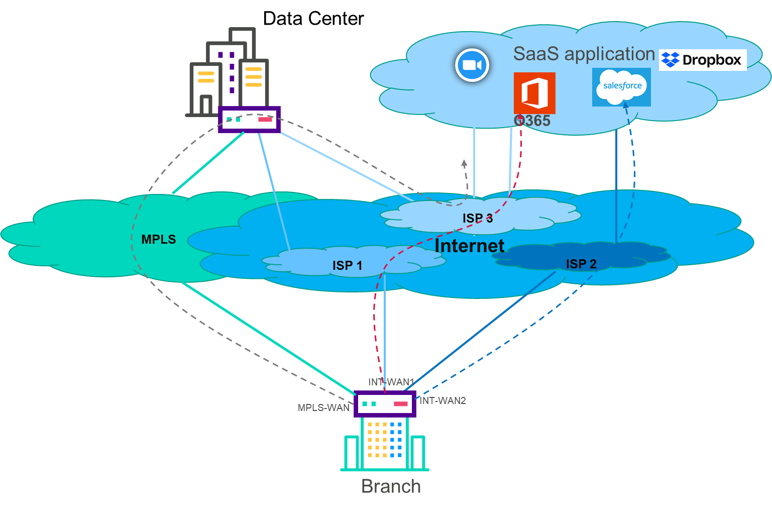
SaaS Optimization & DNS Proxy
DNS Proxy
| This feature provides the customer the ability to configure multiple DNS profiles for capturing queries from the LAN for sending to the selected DNS servers. One example of use of this feature is split DNS by having two DNS profiles. One rule for redirection of queries to internal domains through an enterprise corporate DNS and second to redirect the rest of the DNS queries to external or Global DNS servers. |
A DNS proxy profile is used to provide split DNS functionality. Typically, the proxy is configured to forward all enterprise internal names to a DNS server behind a HQ site, and to forward all external domain names to a public DNS server such as Google DNS or Open DNS. Now a DNS proxy profile can set the “honour-pbf” flag to true to indicate that SD WAN rules should be looked up to determine the path, on which to send the DNS query. For this to work, a DNS resolver needs to be available for each path that pbf can send the traffic on.
The DNS query that happens at the beginning of a web transaction is steered independently. This may result in sub-optimal DNS resolution. For example, consider a use case where salesforce traffic must use local breakout over either LBO1 or LBO2. It is possible that the Versa DNS proxy module independently steers the DNS query over local wan circuit LBO1, and PBF module steers the subsequent HTTP session(s) over either LBO1 or LBO2. Enabling Strict DNS path affinity helps pinning the subsequent HTTP/HTTPS sessions from the end client over same path DNS query resolved. DNS Proxy with “honour-pbf” enabled redirects the DNS query for selective domains, for example Office365, Salesforce & Dropbox and lookup the SD WAN policy rule defined for these applications and determine the path to send the DNS query.
This is illustrated in the diagram below:
The DNS Proxy tab can be found underneath the Policy tab and a specific site screen as shown below.
Once the site has been unlocked then the user can select the 'Add DNS Profile' button and the following screen opens.
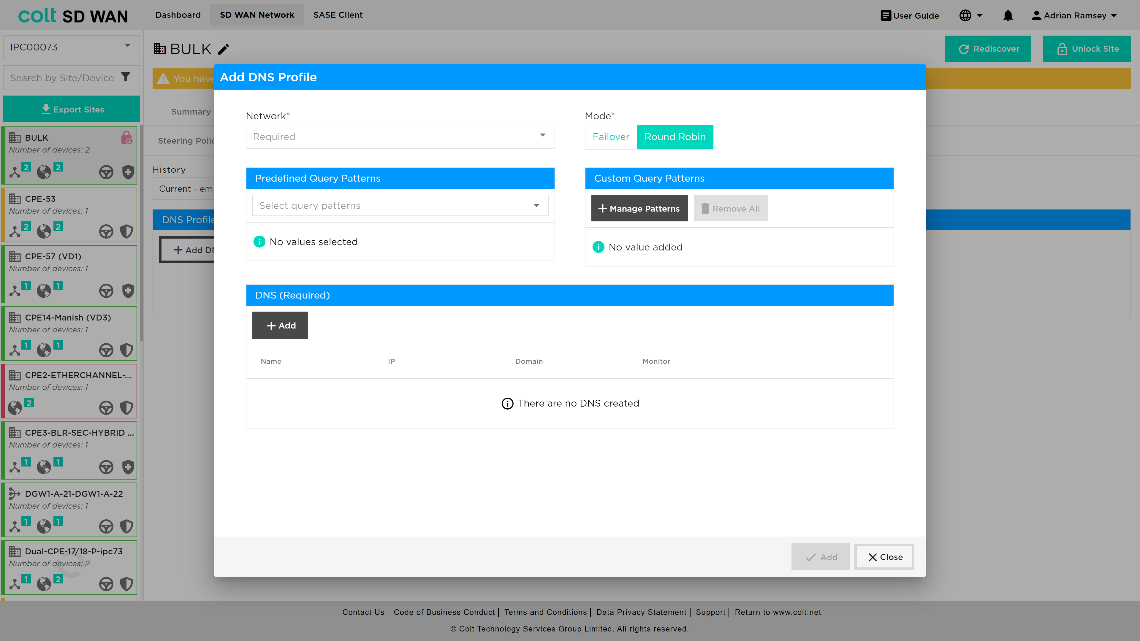
Within this screen the customer needs to add DNS details under the DNS (Required) section. once the user presses the +Add button the following screen opens:
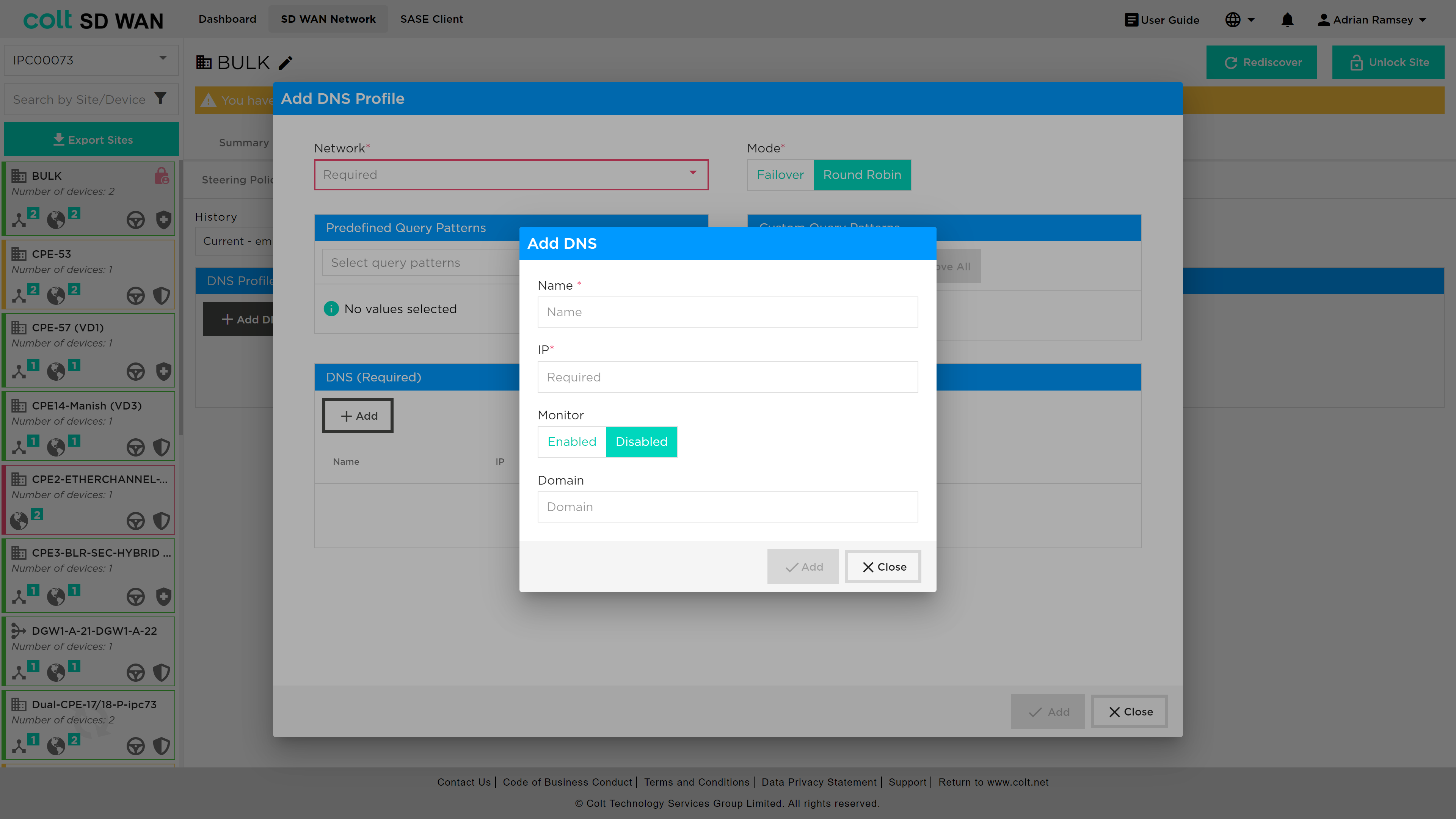
An explanation of the parameters required from the user:
-
Network (Mandatory, single choice): Avaiable associated LAN Networks will be available for single choice.
-
Mode (Mandatory, single choice): Selection of DNS behavior mode if Failover or Round Robin for all DNS configured on the policy.
-
DNS – Name (Mandatory, customer input): Name given by the customer.
-
DNS – IP address (Mandatory, customer input): IP address for the DNS Name mentioned above.
-
DNS query pattern (Optional, Customer input): Customer can provide the DNS pattern for the matching criteria of the DNS queries to be resolved by the DNS’s configured on the associated profile.
SaaS Optimization
|
This feature is designed to improve the current Internet traffic steering rules by providing path selection based on the best performance to specific SaaS Applications. So in comparison with the current Internet traffic steering it is not possible to make a path selection based on the defined SLAs. In order to achieve the internet traffic steering SLA driven policy, we are introducing several mechanisms:
|
In a typical SDWAN deployment, there are multiple WAN-links/paths to reach a given Application and it is important to choose the best path based on metrics collected by an active monitor to improve the overall user experience. While this capability is not available for Internet based applications, using Active SaaS monitor, path selection for selective SaaS applications can be influenced to use local-breakout or remote-breakout to achieve better application performance.
|
DNS-Proxy MUST be configured to enable SaaS steering rules to function properly. In addition: • DNS settings for SaaS applications are able to make use of user selectable predefined DNS patterns in conjunction with customized patterns added seperately • It is highly recommended to configure Global DNS servers for SaaS applications to provide better DNS resolutions |
In order to configure SaaS steering rules it is required to have one of these combinations: • One INT-WAN Link with LIB enabled and CIB from Gateway(s) • Two INT-WAN Links with LIB enabled • CIB on Gateway(s), only in case of the customer wanting to use them as next-hop. So the Gateway must have Next-Gen Firewall enabled for the relevant customer ORG. • On the Gateway(s) SaaS-Application Monitor will already be created for each SaaS-App on the Colt ORG: <SAAS_APP_NAME> and new QoS rules to allow that performance statistic traffic. On Dedicated Gateways this configuration must be configured on the Customer ORG.
| As standard the LAN traffic to SaaS-Apps must be allowed from FW-Rules managed by the customer on the portal for the relevant branch site and Gateway if selected. |
To add a new SaaS steering rule, the user nagivates to Policy → Steering Policies and after unlocking the site presses the '+ Add new rule' button. The following screen opens and the user should select 'SAAS' from the rule type selection at the top of the window.

An explanation of the parameters required from the user:
-
SaaS-Application (Mandatory, single choice): there will be approximately 22 SaaS-Applications available for the Customer to select from.
-
Network (Mandatory, single choice): Selection of the VPN (LAN-VRF) that will be applicable for the SaaS-Policy.
-
Maximum Latency (ms) (Mandatory, customer input value): Integer value in for maximum latency in millisecond of SLA associated to the next-hop defined by customer from 1 to 1000 ms.
-
Maximum packet loss (%) (Mandatory, customer input value): Integer or decimal value for maximum packet loss in percentage of SLA associated to the next-hop defined by customer by customer from 0.01 to 100%.
-
Available INT Transports (Mandatory, multiple choice for drag and drop): All the Internet transports from branch site will be visible at the box to drag and drop to the corresponding priority selected (1-3) by customer.
-
Available Gateways (Optional, multiple choice for drag and drop): All the Gateways available (Only with CIB enabled) from branch site will be visible at the box to drag and drop to the corresponding priority selected (1-3) by customer.
-
SLA Next-hops (Mandatory, multiple choice): in the boxes (Priority 1-3) the items from “Available INT Transport” and from “Available Gateways” will be moved based on the customer preference.
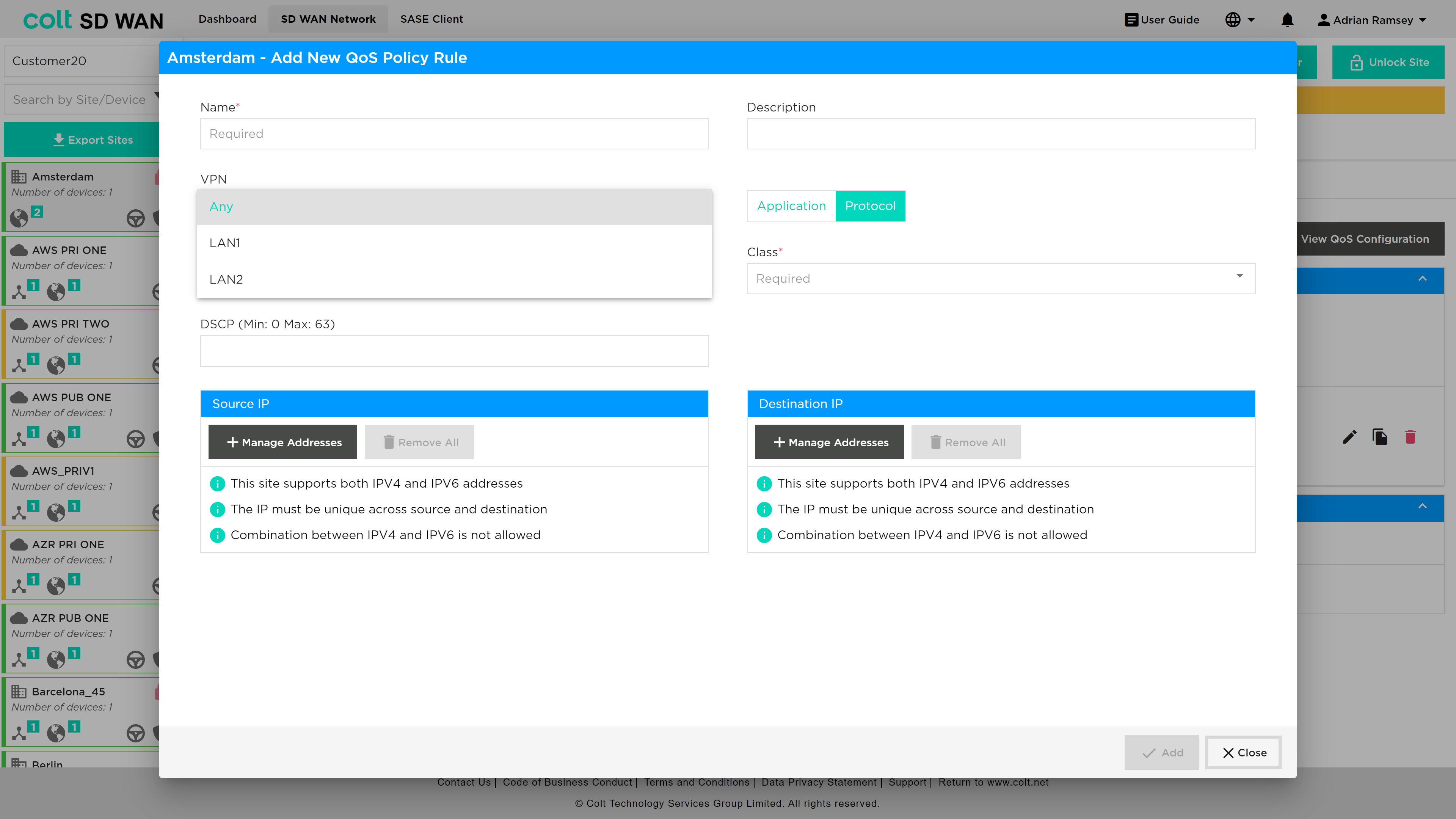
IP QoS Management
IP QoS Management has two aspects to the feature:
-
IP Flow assignment of DSCP value by match of IP address and Ports
-
Application of DSCP per application session
The basic IP QoS configuration allows Colt’s traffic class (Premium, Business 1, Business 2, Business 3) to be forwarding class that matches the IP VPN QoS policy. Application QoS provides session based QoS policy that include the IP Flow policies.
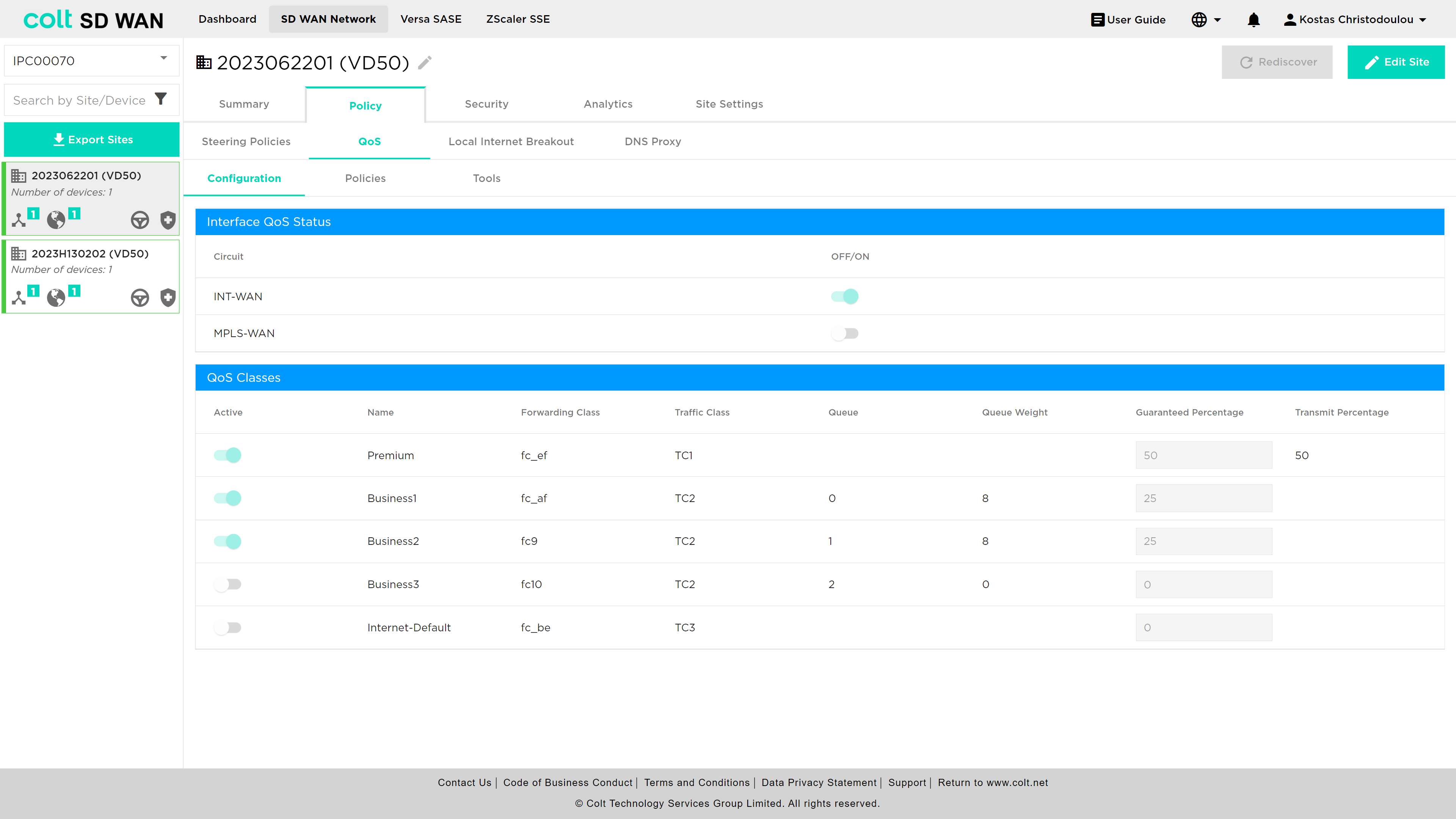
The feature is part of Policy or traffic steering menu options and a sub-menu is available as shown below where IP QoS policies can be viewed, edited, duplicated and set in priority order. The SDWAN service has 4 predefined forwarding classes: Premium, Business 1, Business 2 and Business 3. IP DSCP values are mapped to each class. In addition, each class has a fixed number of queues, queue depth and guaranteed transmit which are not configurable.
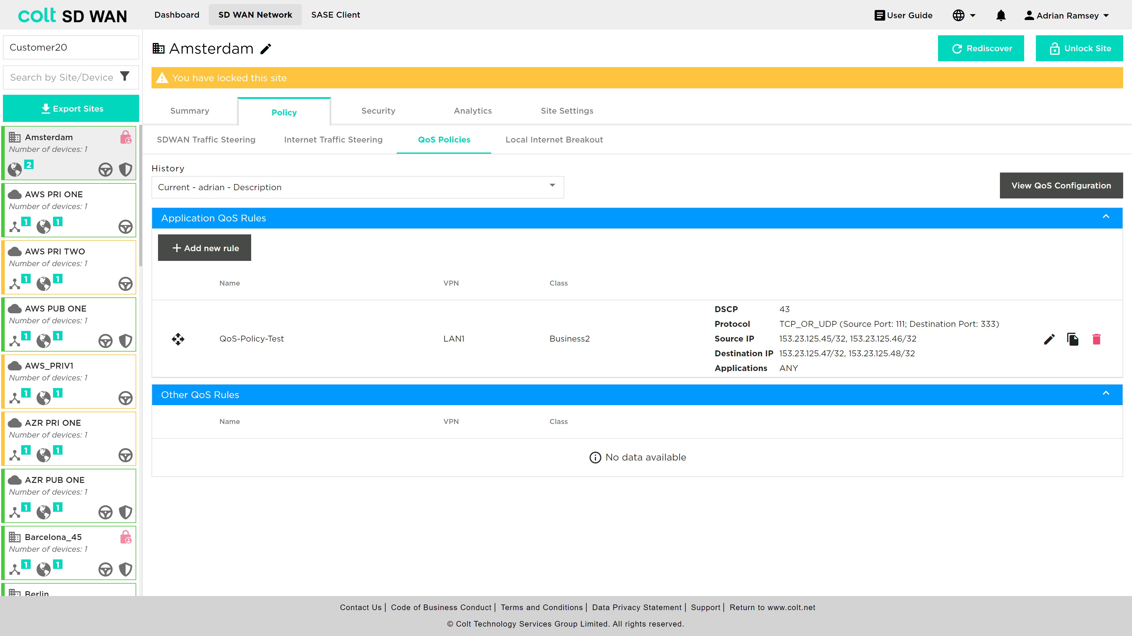
There is View QoS configuration which allows the view of the forwarding class configuration, including the DSCP assignment to each class, associated queues, guaranted bandwidth allocation and guaranteed transmit. The view shows the following:
The process to add or edit a rule uses the same screens and parameters. To add a new rule, select the “Add New rule” button. The rule can be created with the following options:
-
VPN
-
Application
-
Source destination IP address combinations
-
-
Protocol
-
IP address (source & destination combinations)
-
Port number or ranges (source & destination combinations)
-
-
Class of Service
-
DSCP Value
The App QoS allows mapping per application session for IP QoS parameters to be applied to a specifc VPN or LAN VRF (needs high degree of expertise) or to apply to “Any” interface as that site. In the event the customer QoS profile mathes the Colt IP VPN profile no additional QoS policy are needed.
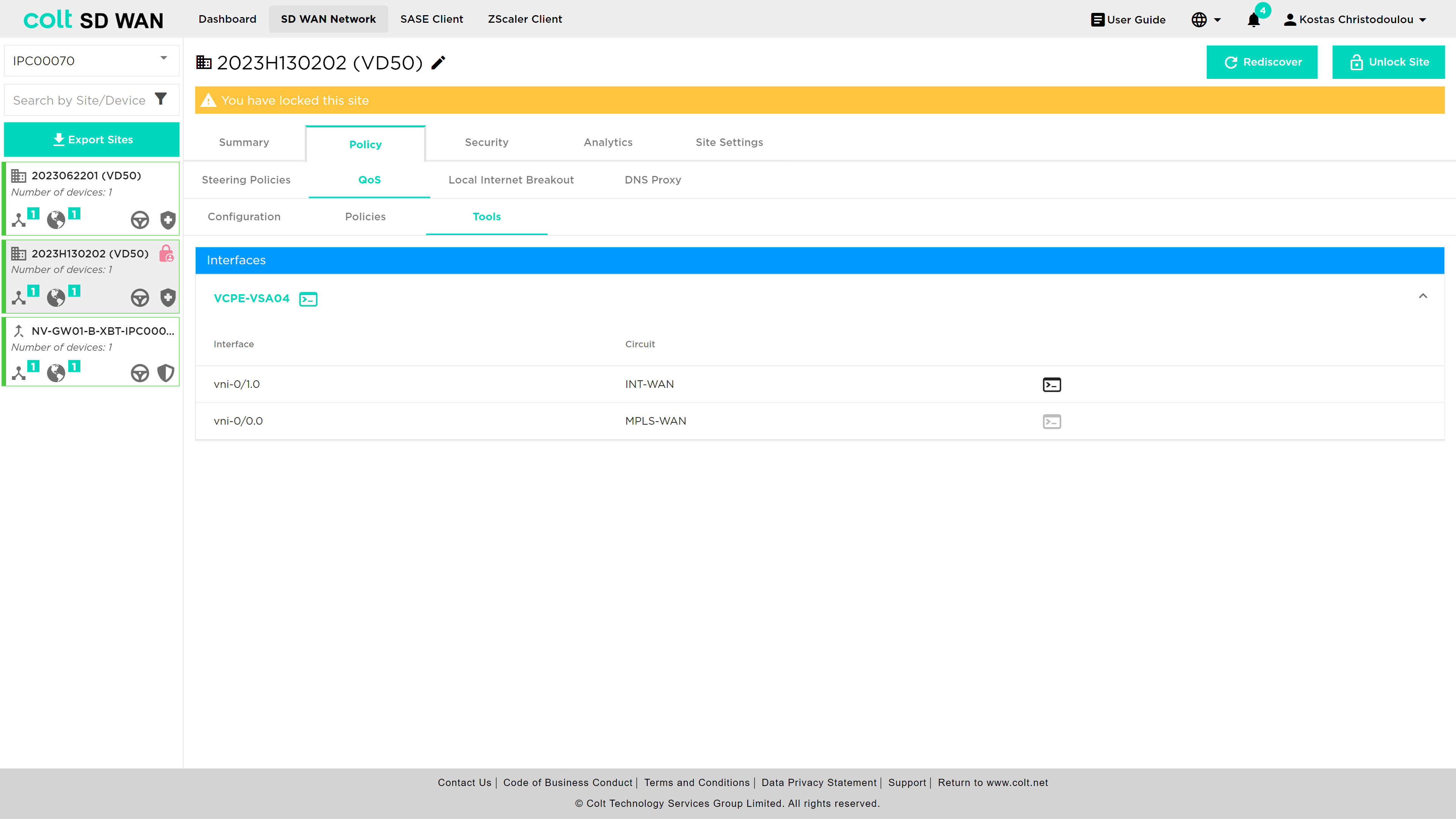
These IP QoS rules can be bulk copied using the Bulk Copy feature, see section here . In addition to Bulk copy the Command line console options now include snapshot views of the IP QoS class and queues, for more information see here.
In addition the Device page has an icon for each CPE that shows the command line output for:
-
QoS Policies
-
App QoS Policies
-
QoS Mapping
Also, the analytics data has IP QoS interface Analytics, see here
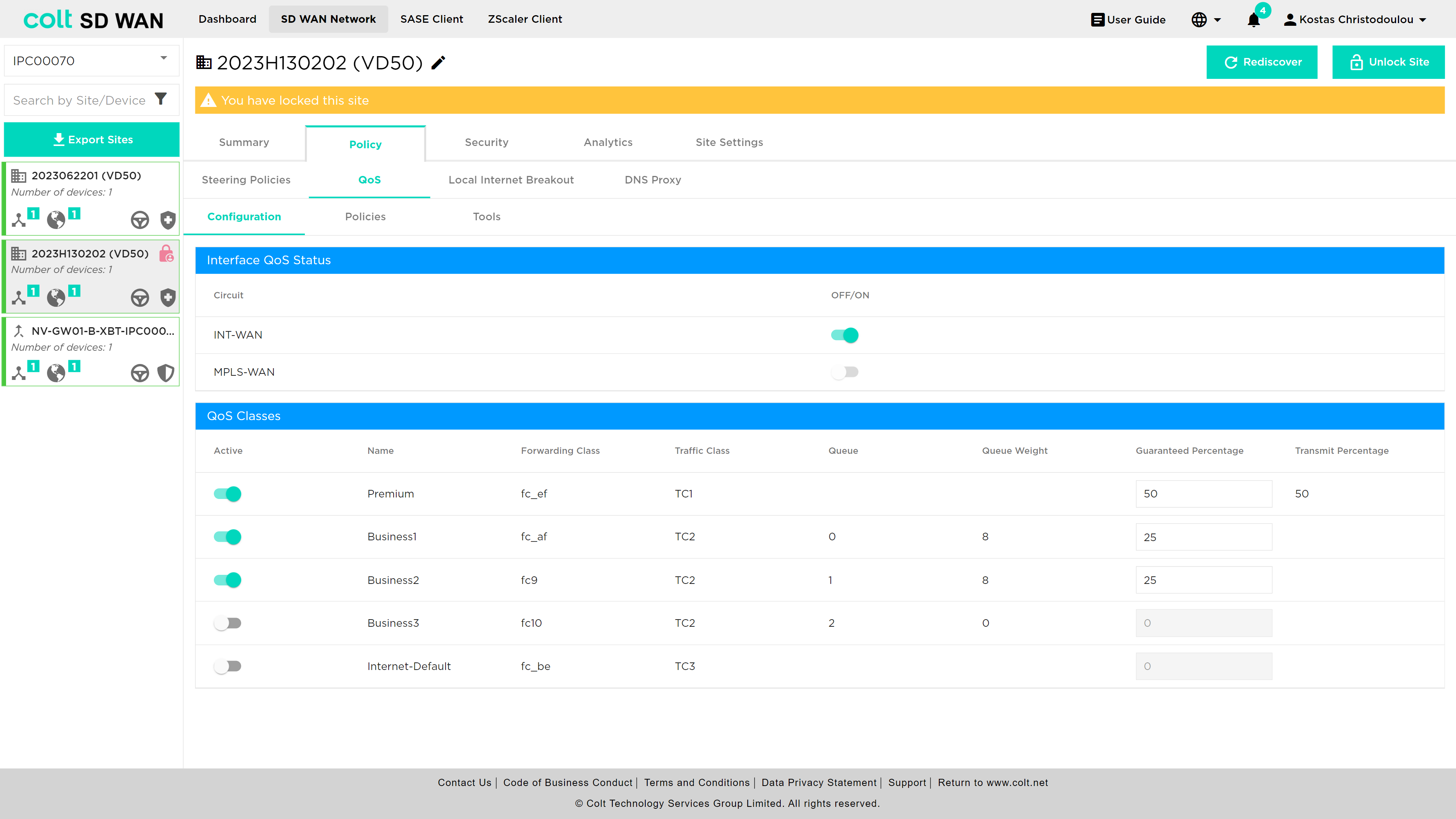
Internet Egress QoS
Internet Egress is a new non-chargeable feature that allows the user to apply Quality of Service (QoS) on the egress (outgoing) traffic of Internet based links of the SDWAN CPE. In the past, QoS capabilities were limited to MPLS networks, providing priority queuing and traffic management exclusively for that type of connection. However, with this recent enhancement, the QoS functionality has been extended to include Internet underlays as well. This means that the user can now apply priority queuing and traffic shaping on Internet connections, allowing for control and prioritization of data traffic. In order to set up Internet Egress QoS, the user´s CPE should have at least one Internet uplink and the configurations listed below:
-
QoS Profiles (Premium, Business 1/2/3, default - customer input)
-
Drop Profiles
-
Schedulers (customer input)
-
Scheduler Maps
-
Associated Internet Uplink(s) (customer input)
-
Classification Rules/Application QoS Rules (customer input)
It is also important to note that the actual configuration impacts the SDWAN CPE and overlay only. Additionally, QoS on Internet links can be configured on the CPE for On-Net, OLO and Bring Your Own links (BYO). Internet Egress QoS, like MPLS QoS, allows traffic classes to be mapped as forwarding classes, effectively ensuring that critical applications or services receive the necessary bandwidth and priority, while less important or non-essential traffic is appropriately managed. The mapping is done as shown below:
| Traffic Class | Forwarding Class | Traffic Class | Traffic Type | Queue | Loss Priority | DSCP Rewrite | Dot1P Rewrite |
|---|---|---|---|---|---|---|---|
Premium |
Forwarding Class 4 |
TC1 |
Highest Priority - Real-time voice and video (eg. MS Teams, Zoom) |
- |
Low |
No |
No |
Business1 |
Forwarding Class 8 |
TC2 |
High Priority - ERP systems, database transactions |
0 |
High |
No |
No |
Business2 |
Forwarding Class 9 |
TC2 |
High Priority - Important business applications, financials transactions |
1 |
High |
No |
No |
Business3 |
Forwarding Class 10 |
TC2 |
High Priority - Critical business applications, real-time data trading |
2 |
High |
No |
No |
Internet-Default |
Forwarding Class 12 |
TC3 |
Medium Priortiy - Web browsing, software updates |
- |
High |
No |
No |
For enabling Internet Egress QoS for the first time, the user needs to navigate to the Policy page and click on the QoS tab.
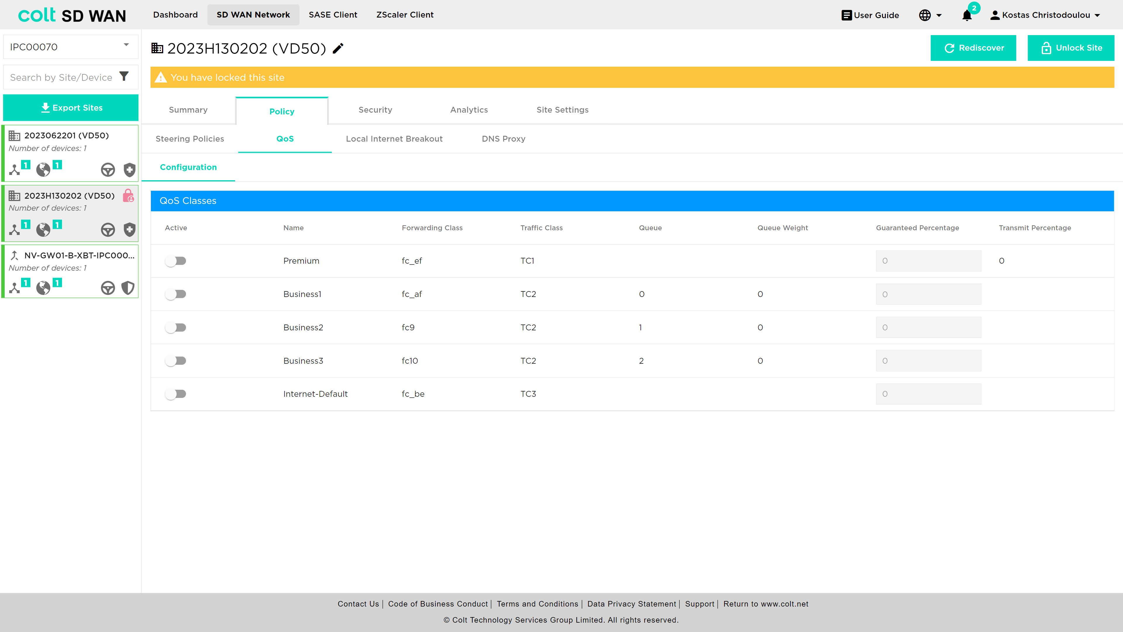
Then the user needs to activate the QoS classes they want and together with the activation of the classes, a new table will appear and the Interface QoS Status can be switched on/off.
In addition, the execution of QoS commands has now been moved from the Summary page to the Tools section under QoS.
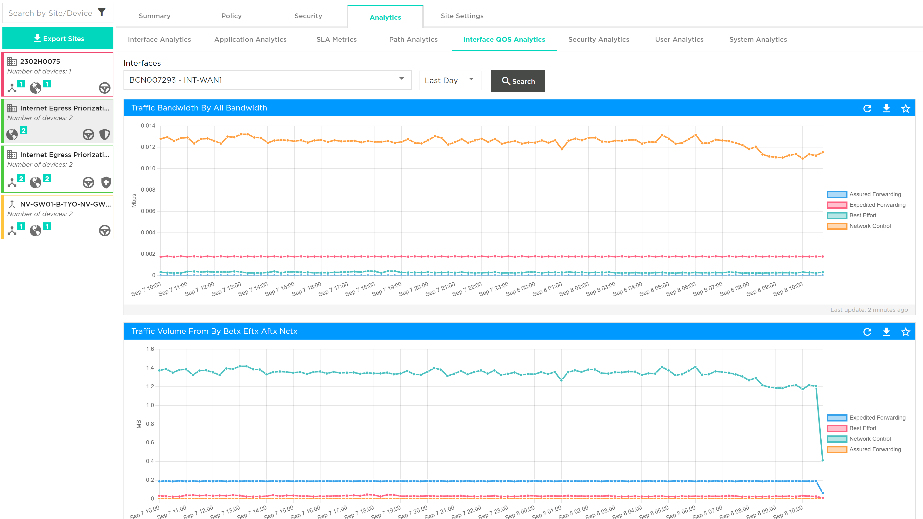
Last, the display of Internet WAN QoS Logging will be in the Analytics tab, under Interface QoS Analytics. See picture below:
The following Use Cases, describe the scenarios where Internet Egress QoS can be applied:
Use Case 1: QoS Internet Site only Scenario 1: If at least one Internet uplink exists, the customer can configure QoS on Internet Egress. The necessary configurations/steps 1-6 are mentioned above. Scenario 2: If there are more than one Internet uplinks, the user can configure QoS on all available uplinks separately.
Use Case 2: QoS Hybrid Site Scenario 1: If there are MPLS and Internet uplinks, but no QoS enabled, the customer can configure the Internet QoS only, for MPLS configuration Colt SD need to configure. Scenario 2: If there are MPLS and Internet uplinks and QoS is enabled on MPLS, then the internet uplink will inherit the QoS attributes of the MPLS link, after enabling Internet QoS. Scenario 3: If there is a hybrid site with no QoS configured, the user will be able to configure Internet QoS only.