Portal Overview
Portal Page Views
The Colt SD WAN platform allows customers to check all the services that have been requested, and the status of each of these services. Customers can use the portal to edit traffic forwarding (over MPLS and/or Internet), set forwarding thresholds, view and edit Firewall policies and see Firewall, interface, DDoS and application analytics.
The portal is being continuously improved under Colt’s agile programme and will be updated without notification. Customer functionalities will not be impacted by these changes.
Dashboard
Portal Users first log into the dashboard view of the entire customer SD WAN network. The view shows a listing by customer sites and a dashboard view which users can customize. By default, the Dashboard view is empty until users attach or pin any graphical reports to the Dashboard.
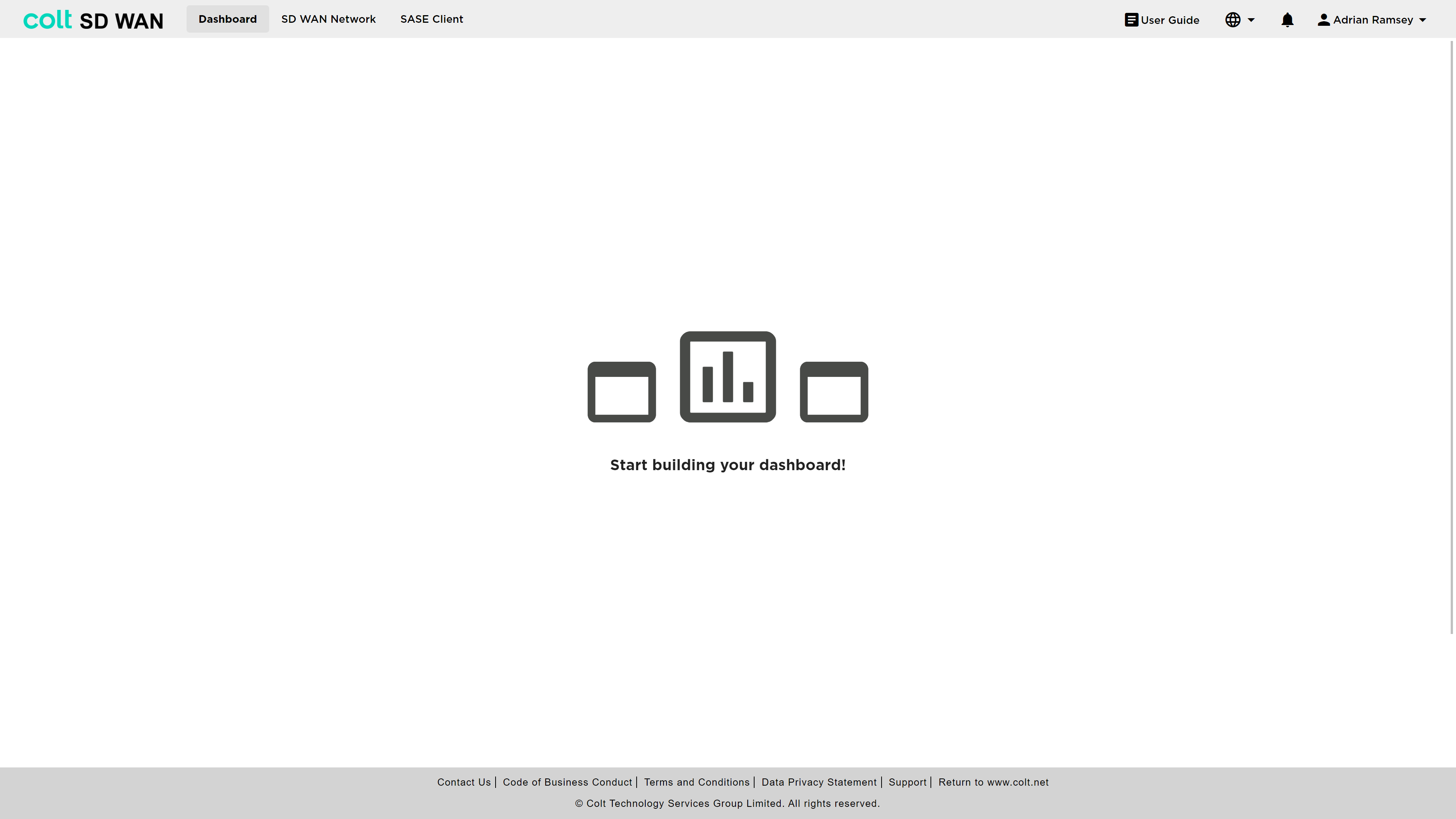
To access site level information, policies, analytics or IPC’s a user needs to select the main menu option “SD WAN Network” as shown above. The following sections illustrate the various options and configurations available.
SD WAN Network Navigation
The SD WAN Network is accessed via the main menu and renders a page view showing the list of IPC’s available and which can be selected to change the view of the list of the available devices in each IPC. Each IPC also has a list view of all the available CPE locations shown. The icon symbol for each location contains icons for:
-
MPLS WAN
-
Internet WAN
-
Steering rules
-
Firewall rules
-
Cloud or branch sites
When sites are being updated a wheel is displayed in the site icon to show updating.
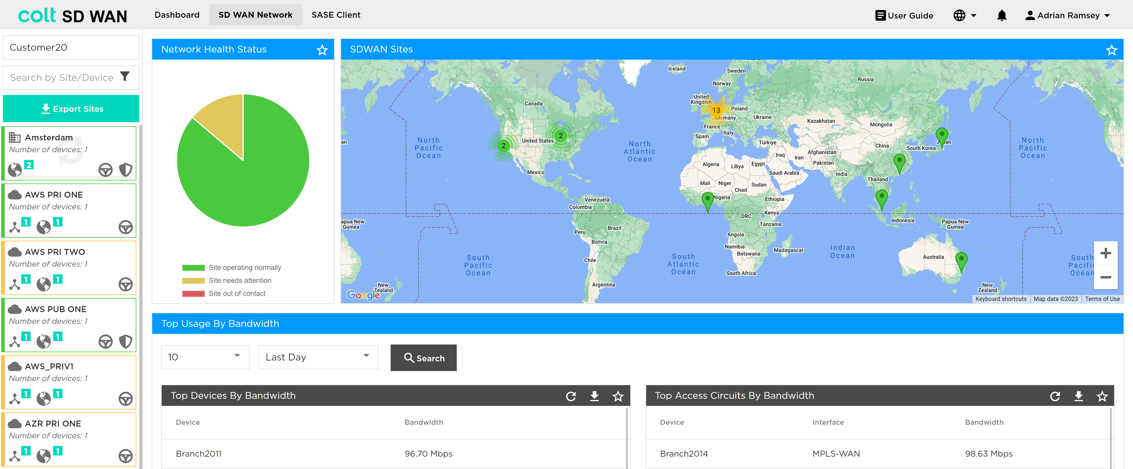
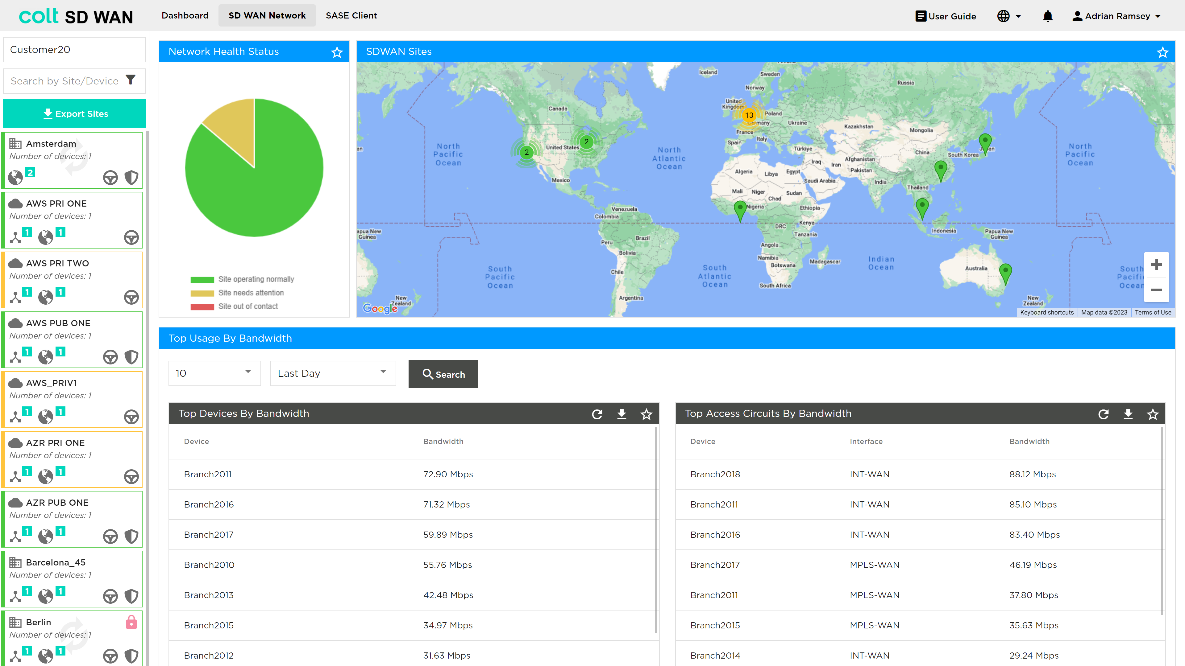
In addition, there is a network (IPC) health status window and graphical map view with icons showing location and colour coded for status. The map icons can be selected which then open a popup window showing the site name as a link and the WAN configuration.
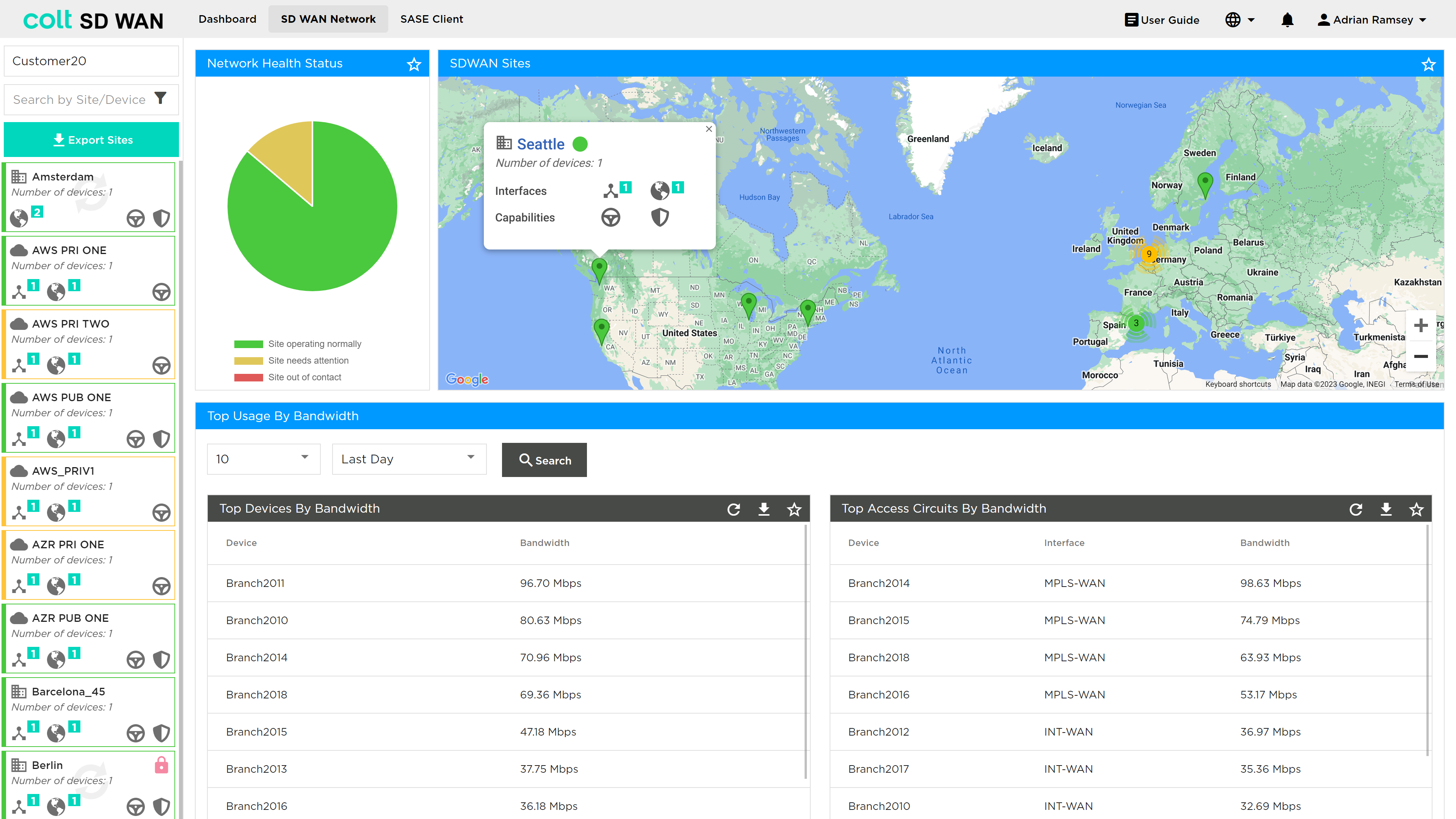
Portal Users can scroll through sites using the scroll bar and click to select each site or search by name. The initial views shows:
-
SD WAN Network Health status
-
Map View of SD WAN sites
The Network Health status is colour coded as follows:
-
Site Status Green if the following criteria are matched
-
If all the associated devices are in SYNC and Reachable and
-
If all the associated devices WAN & LAN uplinks are UP and running
-
If in Dual CPE scenarios one of the devices is not fully configured and a WAN link is admin-shut
-
-
Site Status Red if any of the following criteria is matched
-
If any of the associated devices are not reachable
-
If any of the associated device is not in SYNC and all corresponding LAN & WAN uplinks are down
-
-
Site Status Amber in all other cases like
-
If any of the associated devices WAN & LAN Uplink is down while all the associated devices are in SYNC and reachable
-
If in Dual CPE scenarios a WAN port is not admin-shut and is DOWN
-
| The Standby feature allows the secondary WAN interface (typically Blue Wireless) to remain completely inactive, while the primary internet link is operational. This ensures that the backup link only activates if the primary fails. In the SD WAN portal, sites using this configuration will appear green when the primary link is up, even though the secondary interface is down. This behaviour is expected and does not indicate a fault. |
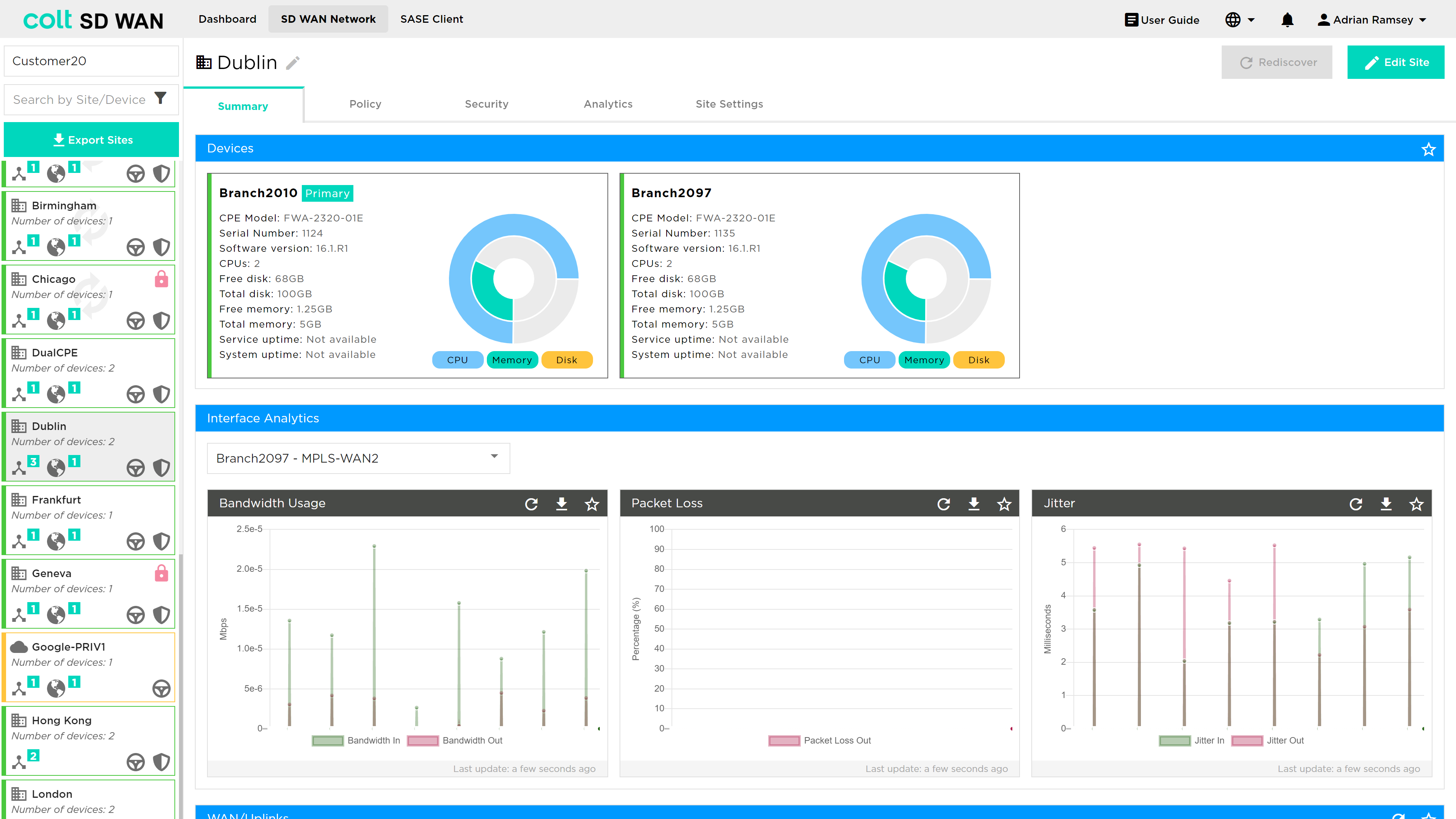
On clicking on a site, a new window appears in the Dashboard view showing all the features available at that site, such as:
-
Summary
-
Policy
-
Security
-
Analytics
-
Site Settings
| These menu options will vary depending on User roles and services that a customer subscribes to. The user roles are as follows: |
| Role | Description |
|---|---|
SD WAN Read Only |
Allows users read-only access to the SD WAN Portal including all sections of the portal, but not allowed to change any parameters. |
SD WAN Manage Traffic |
Allows users full read-write access to the traffic steering / WAN optimization sections of the SD WAN Portal. |
SD WAN Manage Security |
Allows users full read-write access to the security / Firewall sections of the SD WAN Portal. |
SD WAN Manage Self-Install |
Allows users to perform self-install actions of new devices in the SD WAN Portal. |
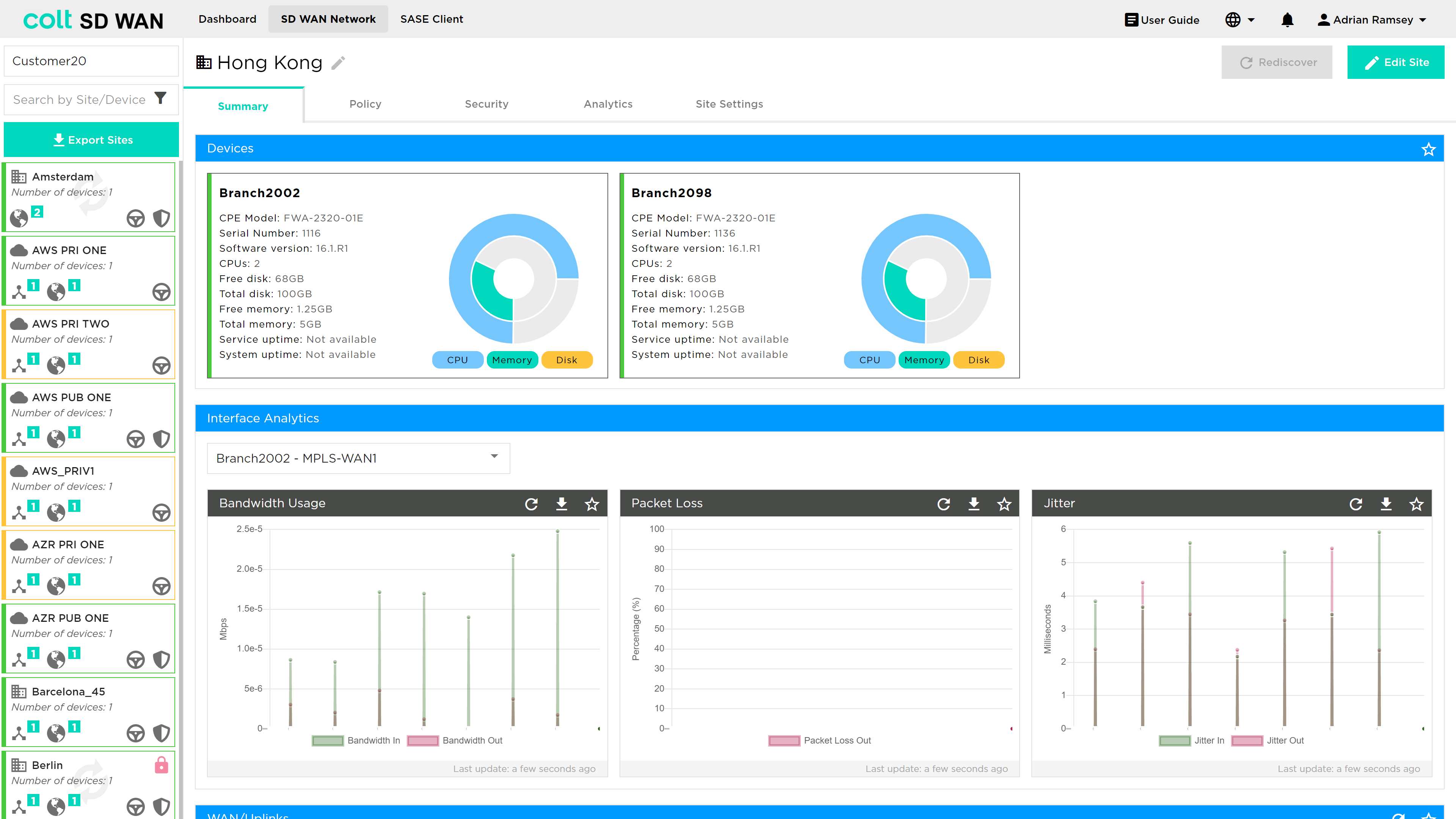
Summary Page
The Summary page view shows as in the photo below:
-
The sites
-
The VPN or IPC health status
-
Top sites and circuits by usage
-
Export Sites button
| The export sites button allows to download information about the Sites, Devices, Circuit References and Interfaces on an .xlsx or pdf format. The report includes, interface and site names, type, features enabled, status and more. |
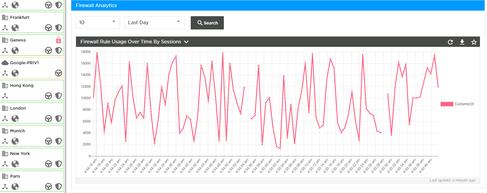
In addition, there is the ability to view aggregate Firewall usage statistics, as well as to view and edit Bulk copy rules.
Policy or Rule Changes and Bulk Copy
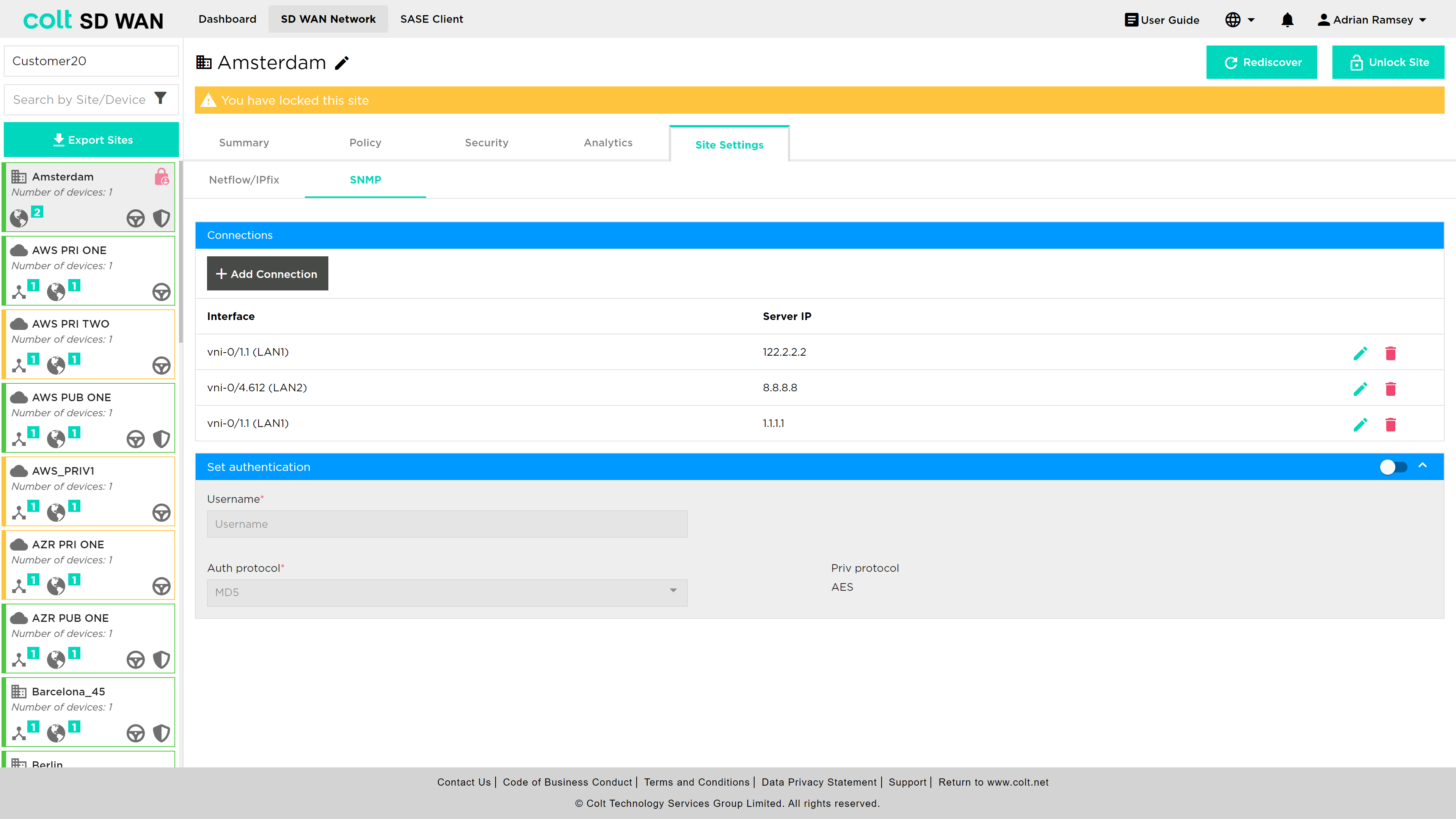
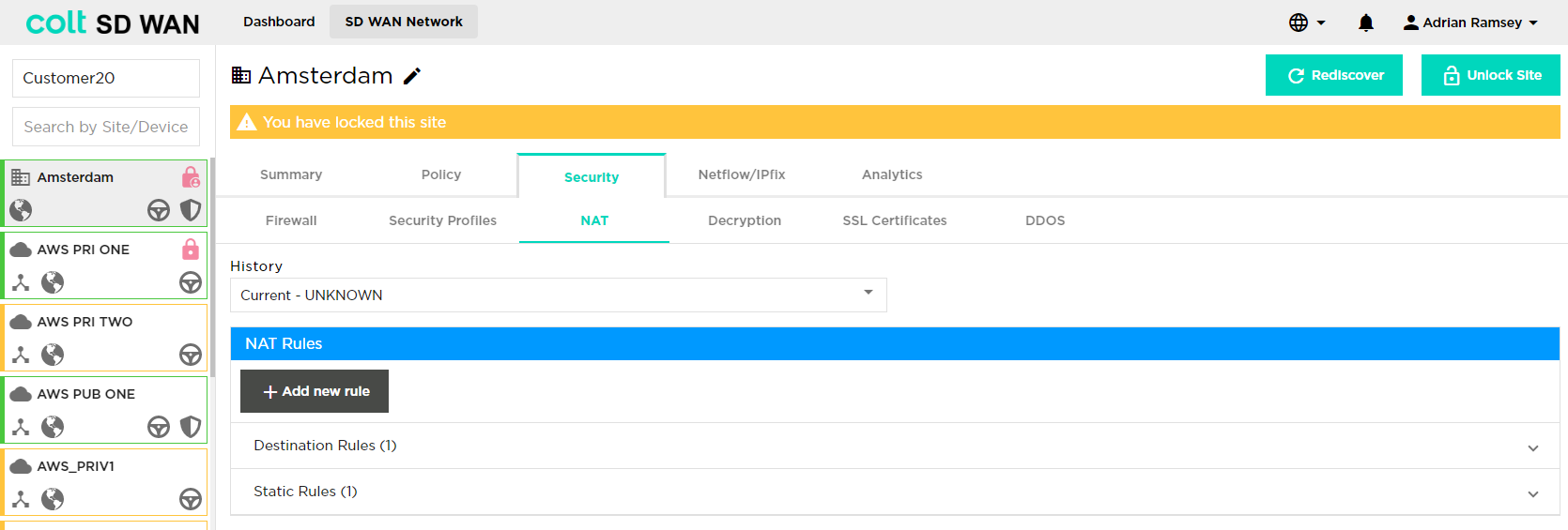
One important change in the SD WAN Portal is the requirement for each user: if they need to add or change a policy, they MUST lock the site by pressing the Edit Site button. This ensures that no other user can edit that site while changes are being made.
Once the Edit Site button has been selected, the user will be notified the site is locked, as shown below:
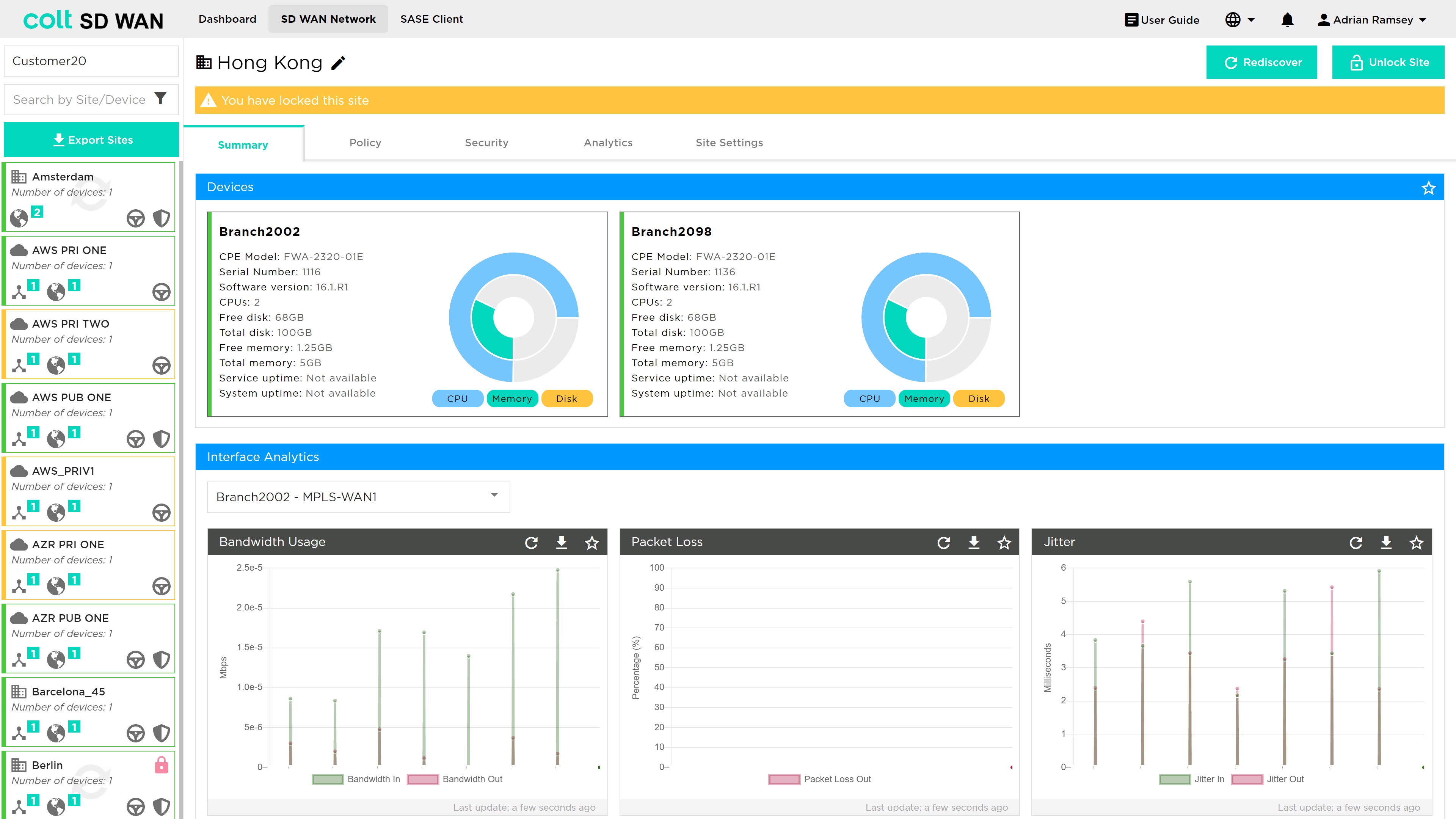
All Policy or Rule change functions, such as “Add Rule” or Edit Static Routes become available, for example.
Any Traffic management policy, IP QoS, NetFlow or Firewall rules can be copied between sites of the same WAN and LAN configuration. The feature is available from the SD WAN Network page and is located at the bottom of the main view page as shown below. The bulk copy shows a history of the bulk copies and the details of each transaction can be viewed by clicking the view details button.
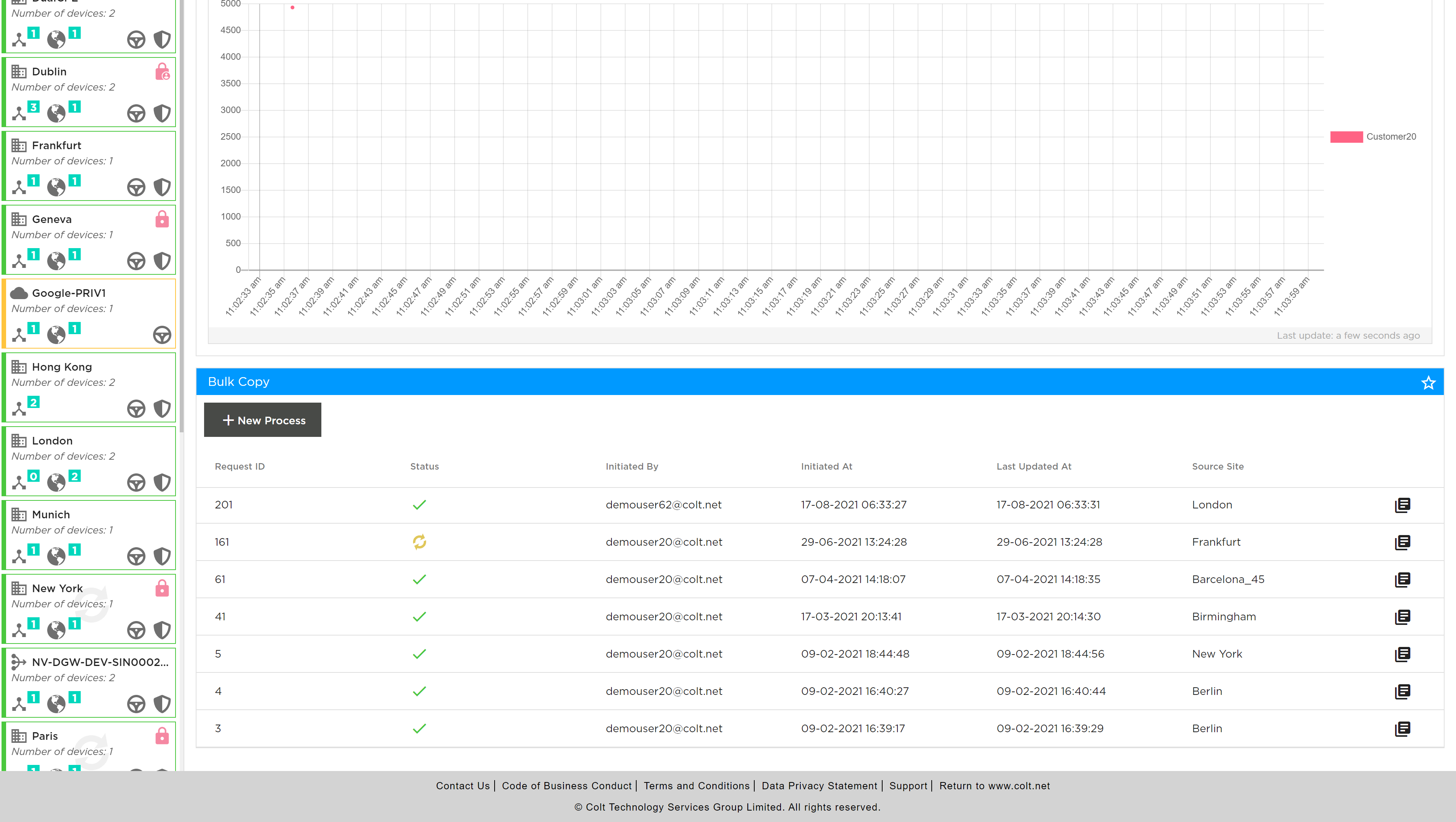
Bulk copies of rules can be created by selecting “+ New Process” button, note the site edit or locking does not need to be done for adding new Bulk Copy transactions. The adding a New Process starts the creation process by opening the following screen where the source of the rules can be selected. The type of rules available at the originating site are: traffic steering, Internet steering or Optimization, NetFlow, and for firewall the basic access control or advanced firewall including NAT, DDoS and IP QoS.
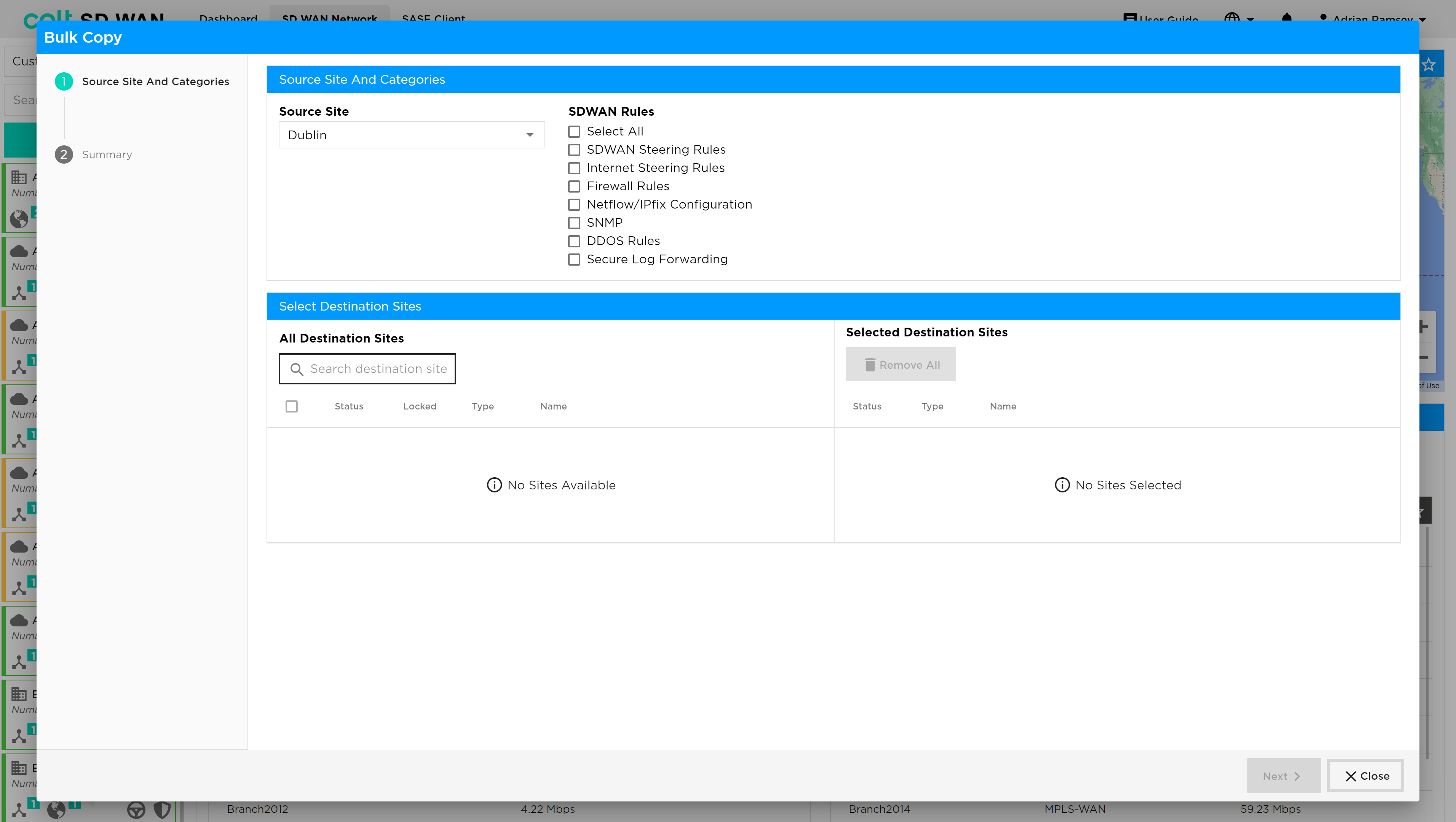
Follow the process as shown on the left hand view screen, note that this will vary in the number of steps, as each site may have different combinations of Firewall, Policy and DDOS features enabled. The Originating and Terminating sites can be entered manually. The destination sites need to manually be selected by using the check box.
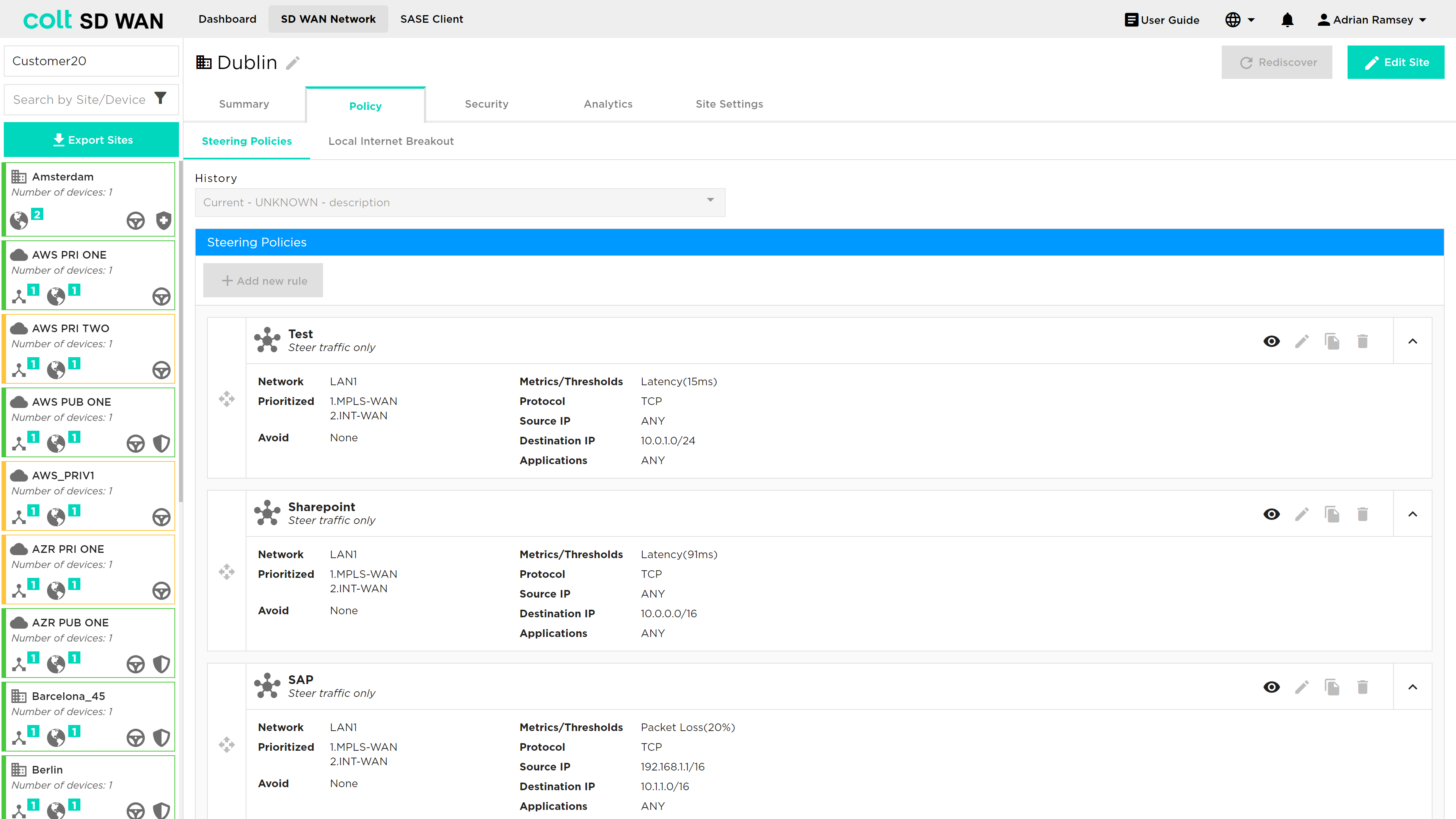
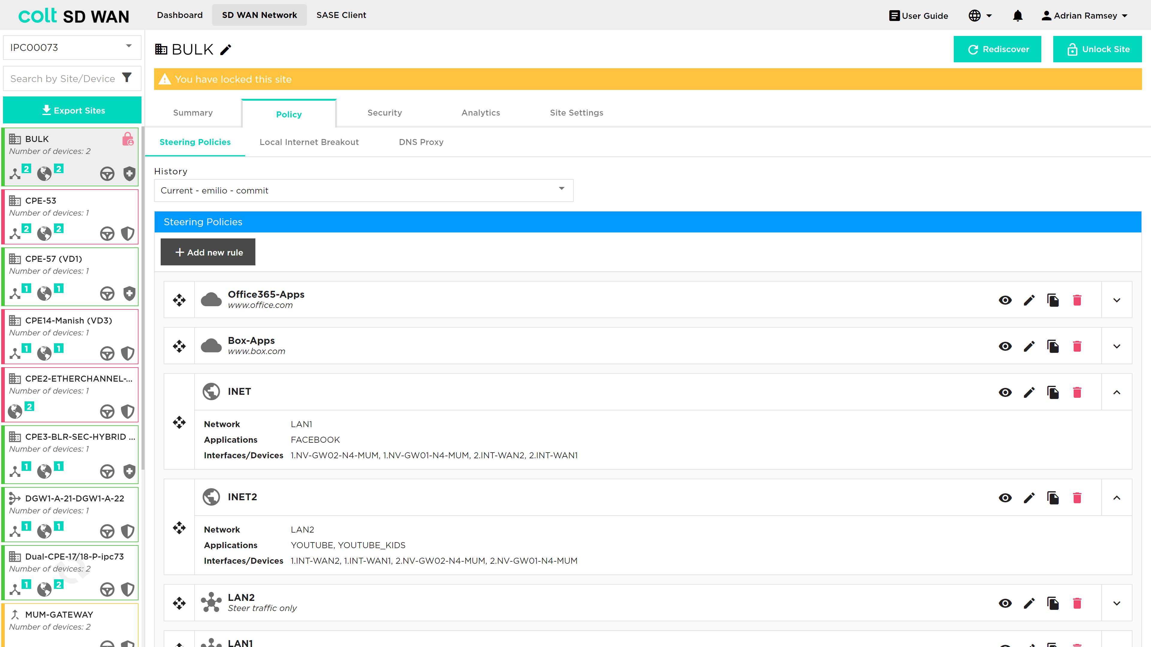
Policy Management
| Policy management provides multiple types of service that can be managed: Traffic Steering for SD WAN, Internet and SaaS applications, Central and Local Internet Breakout, Dedicated Gateway, Quality of Service (QoS) and Traffic Optimization. These are separate services managed via the same portal page. |
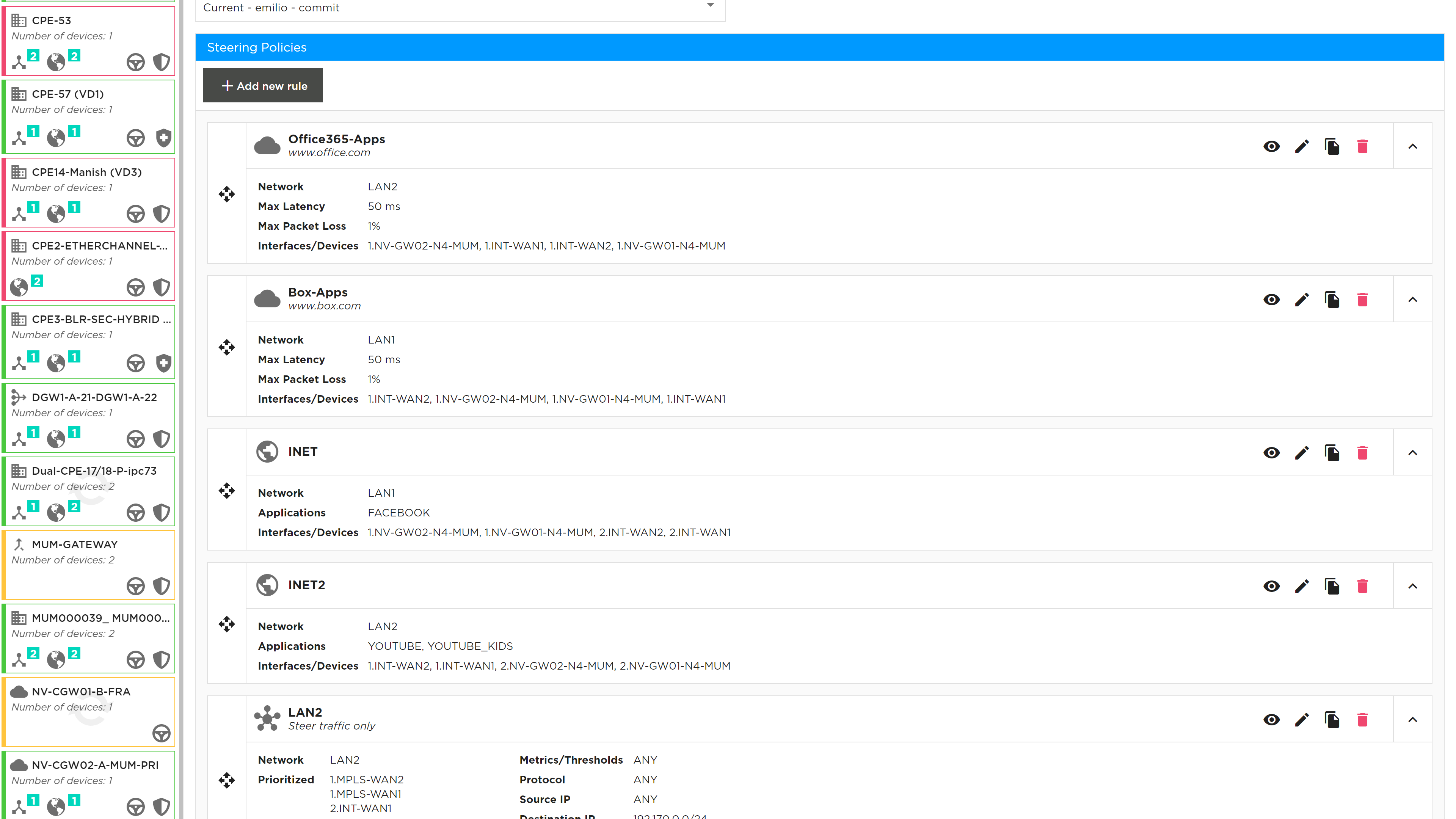
This page shows the list of traffic routing/forwarding policies; policies can be created, viewed, added, edited or deleted by portal users with the appropriate access permissions. Each of the existing policies show the interface order priority and SLA match criteria used to trigger traffic steering. On violation of any single metric traffic is steered to the next interface in the priority list.

While most policy properties can be edited, some features are disabled and need a specific service request – see below for details:
-
Metrics: Available metrics are Latency (milliseconds), Jitter (milliseconds), packet loss (%), Transmit Utilization (%), Receive utilization (%) and MOS score (0-5).
-
Threshold, as shown under metric, is the level at which traffic for that application will switch to the secondary link.
-
Primary Interface is the interface that application will use until a threshold is exceeded or there is a failure on the link
-
Secondary Interface is the failover from the primary interface when a threshold is exceeded
-
Policies were provided when the service was ordered. If there are no policies traffic will be load balanced across the links.
| Existing policies can be viewed but not edited, likewise new policies can’t be added until the “Edit Site” button has been selected to unlock the site. |
The Policy management tab allows source and destination IP/port combinations plus application level steering policies. The application signatures are provided by Versa using the SPACK process which automatically updates the application list.
The default behaviour of traffic routing is to load share across all available interfaces. The steering policy provides a default rule to ensure that traffic can be directed to avoid LTE interfaces and make use of the MPLS and Internet connections using the default rule.
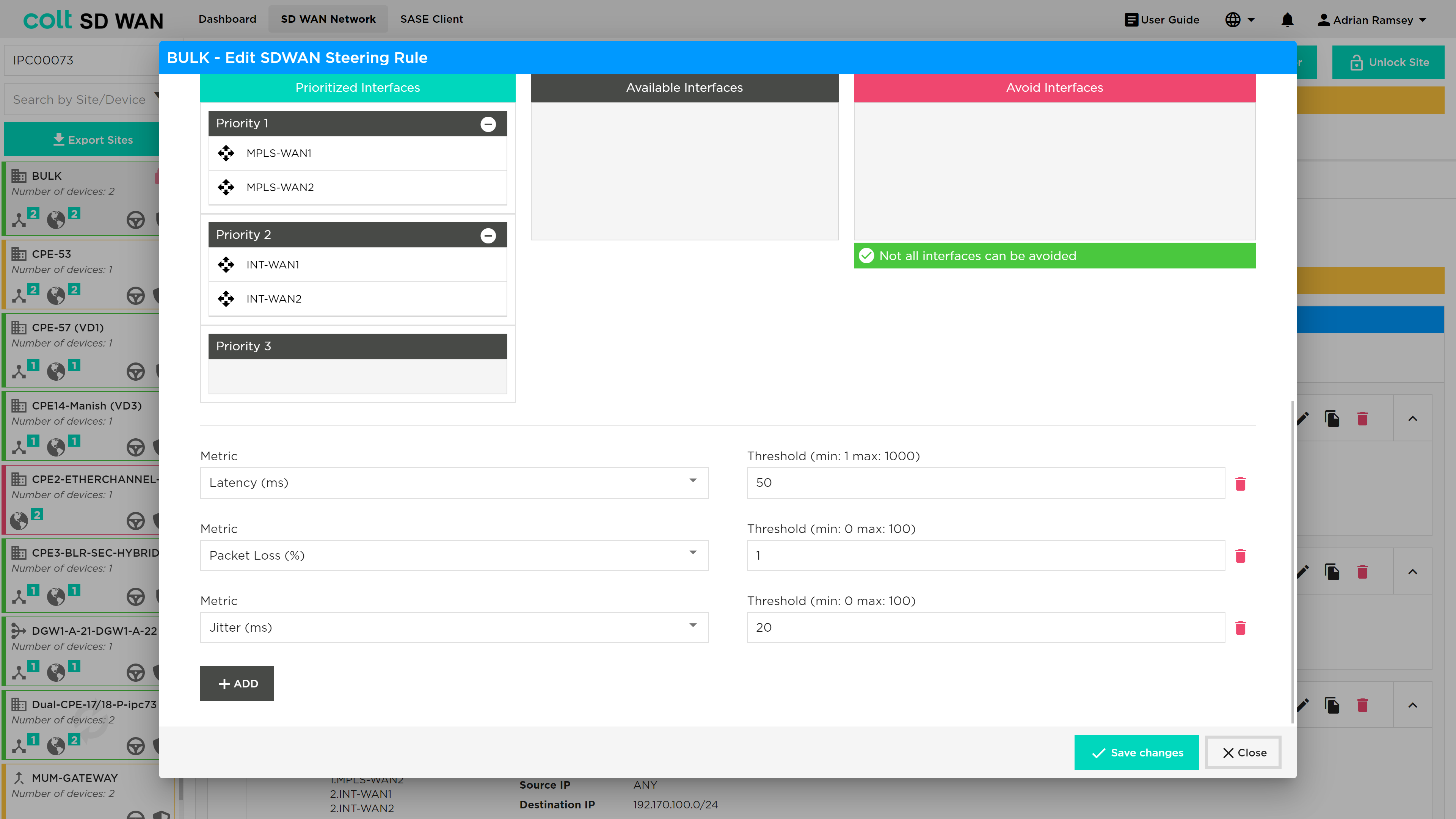
Multi WAN links introduces the option for an SD WAN Portal user to select the number and priority of each WAN interface they want to use or set to avoid when creating traffic steering rule. The screen shot below illustrates the new options.
Single or Dual CPE with Multiple WAN Links can also have default steering rules that allow Multiple uplinks of the same transport domain to be grouped and combined. For example, Dual Hybrid could have a default rule that allowed 2 MPLS links to load balance traffic. This allows for the example below priority 2 links to be used for traffic steering rules.
The traffic steering policies allow traffic to override the default traffic load sharing behaviour by routing based on:
-
Interface priority list
-
Protocol
-
IP and Port
-
Application
Traffic Steering
To edit the parameters, select an existing steering policy and the details will become visible with the options to edit or duplicate the policy. Note to enable editing of rules a user must first use the “Edit Site” button to lock the site from being changed by other users.
If you select edit, a new window will appear to allow the parameters selected for the policy to be edited.
All Source and Destination IP fields can now be entered as a list of IPs, they don’t need to be added one by one. This changes what applied to all the Source IP and Destination IP fields in through the portal
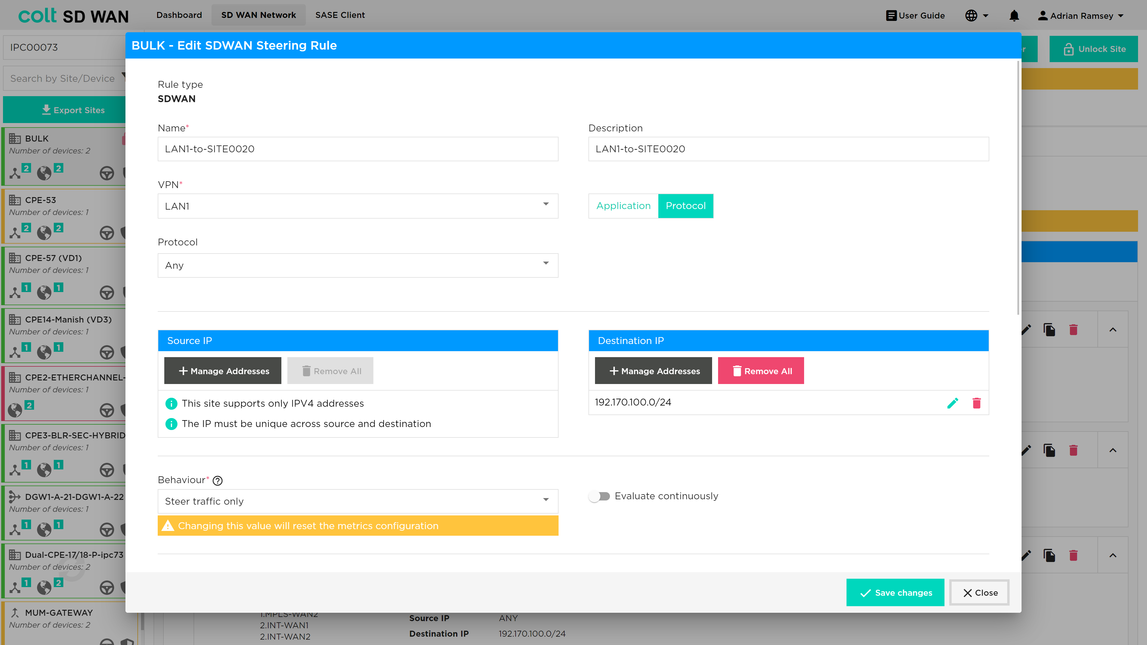
New traffic steering rules can be created by selecting the ‘Add New Policy Rule’ button on the top left of the Policy page which will open the screen as above when you edit pre-existing rules. The create policy allows the creation of traffic steering rules of type:
-
Name
-
VPN – drop down list of VPN labels or friendly names
-
Description – user defined description to label each policy
-
Protocol – Applied to source and destination (IP and ports)
-
Protocol list – Limited list and once selected the Port number boxes will become available to configure
-
Application – Pre-defined lists of applications which can be selected by search or scroll. Applied to all or by source and destination (IP and ports)
-
Interface Priority list
Traffic steering matches an IP address from a VPN to an application or IP protocol/port combination. It then allows that specific traffic to be routed in a priority interface list, overriding the default traffic load balancing behaviour of the SD WAN service. Traffic steering is applied to sites with more than one available WAN link. The metrics provide thresholds that trigger traffic to be steered to the next WAN link in the priority list. There is an option to ‘Avoid’ certain WAN links for specific traffic steering rules.
To create rules, you need as a minimum the following fields:
-
Name – Representative text or number, no spaces
-
VPN – A source interface for the traffic LAN or DMZ
-
Protocol or Application selected
-
Interface 1 and Interface 2 as priority list
-
Metric – At least one metric type to specify the SLA threshold to steer traffic
If Protocol ‘Any’ is selected and no IP address or port numbers specified, all traffic from that VPN will be steered using the Interface priority list and metrics
Multiple source and destination IP address can be created to match in a single steering rule by using the ‘add +’ buttons.
Local Internet Breakout (LIB) traffic is routed based on IP route options defined outside of the scope of the SD WAN Portal.
Multiple metrics can be applied to each new rule be adding a Metric using Add option underneath each metric.
| Navigate to Policy and click on ‘Add new Policy’ button, click on Metric dropdown, make sure the ‘MOS score’ option is enabled for VoIP enabled devices. |
| VoIP Traffic is subject to the default per flow load-balancing inherent to the SD WAN solution so VoIP calls (SIP and RTP flows) to and from sites with multiple transports will be load-balanced across the available paths which might lead to inconsistency in call quality. To override this behaviour the customer needs to manually define traffic steering policies first for their sites that are using VoIP and secondly in the Gateway to ensure symmetric behaviour. This can be done by customers via the Colt Self Service Portal and it´s advisable to use the MPLS transport whenever available. |
The ‘Evaluate Continuously’ option will be visible for all types of devices for which policy is enabled. The option allows the SD WAN path SLA or metric to be monitored and tested periodically if Evaluate Continuously is not selected (the default setting) or continuously if it is selected. This is recommended for VoIP or applications with media codecs.
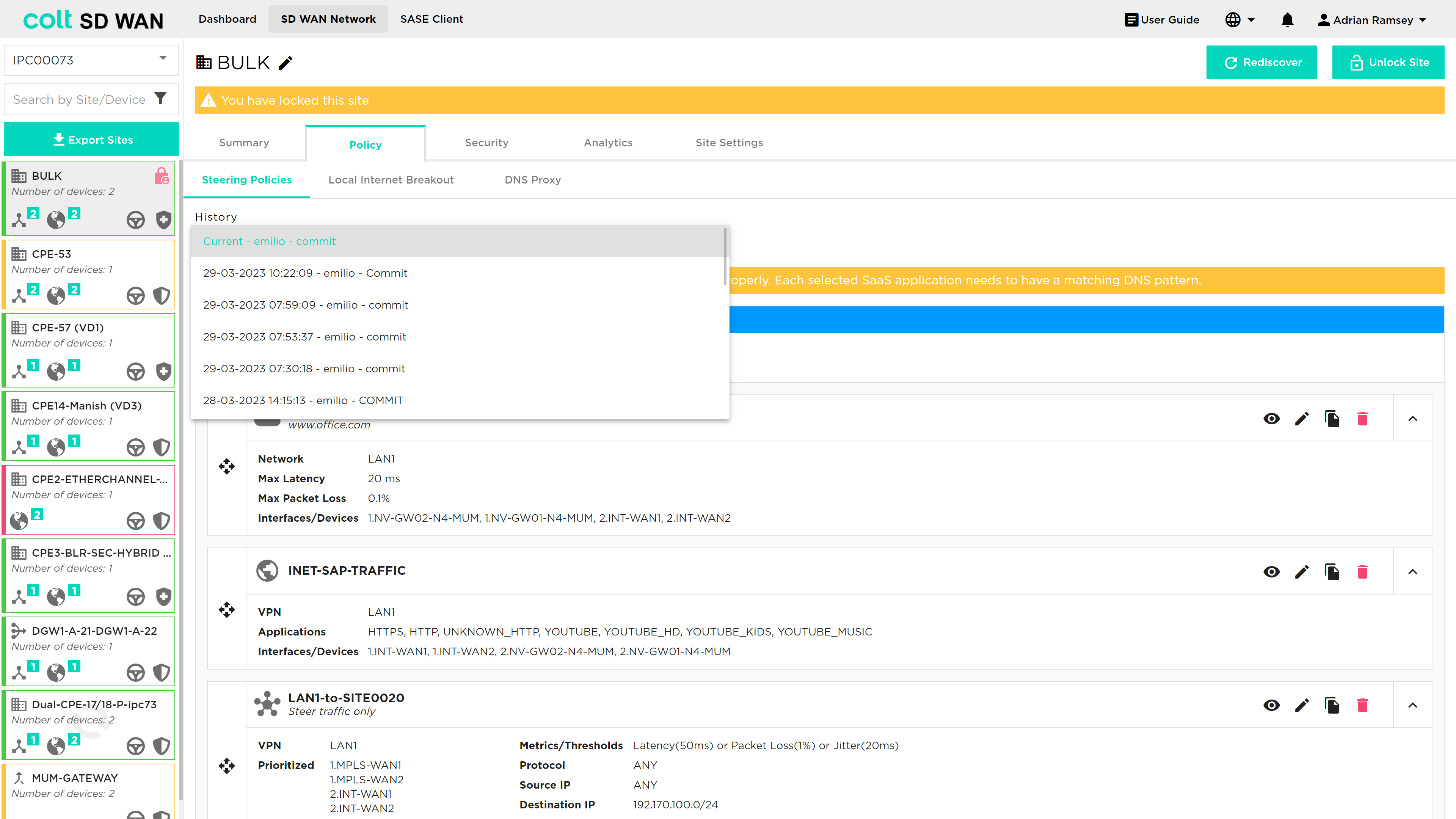
You can view and roll back past changes to policy configurations by selecting history button to view the log of policy changes. Selecting a policy log will display the list of steering policies captured before the policy as changed. These policies can be enabled by selecting the save changes button.
Optimum Path Selection
Optimum Path Selection is a non-chargeable feature that provides the best path selection between all available paths when a 10% variance in performance is reached. This is a variation to the standard SD WAN traffic Steering rules where the path selection for traffic is based on circuit priorities and/or SLA thresholds instead of performance. Optimum Path Selection can steer traffic automatically based one or several metric(s), for example lowest latency, lowest packet loss or lowest delay variation. Dynamic path selection can be selected from the same page in the portal as standard SD WAN steering rules.
Configuring of Optimum Path Selection has a number of dependencies:
-
More than one WAN Transport link enabled
-
Selection of at least one of the metrics from the SLA Profile: Low latency, Low packet loss and Low jitter selectable using the portal
-
The same SLA profile that today is created and associated with the policy when the SLA metrics are configured in the portal is needed for Optimum Path Selection
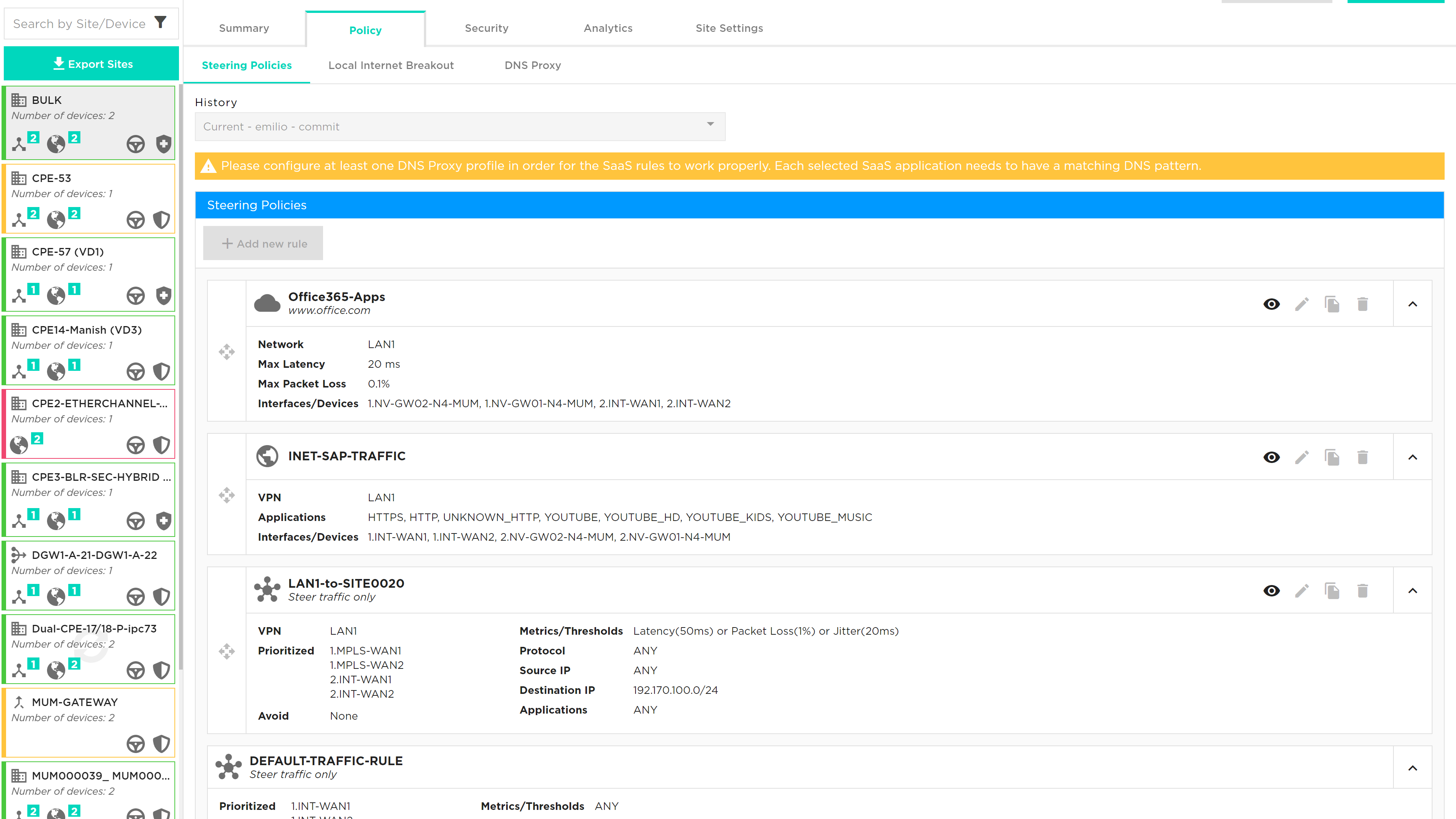
To select Optimum Path Selection, the user navigates to the Steering Policies page, found under the Policy tab as shown below:
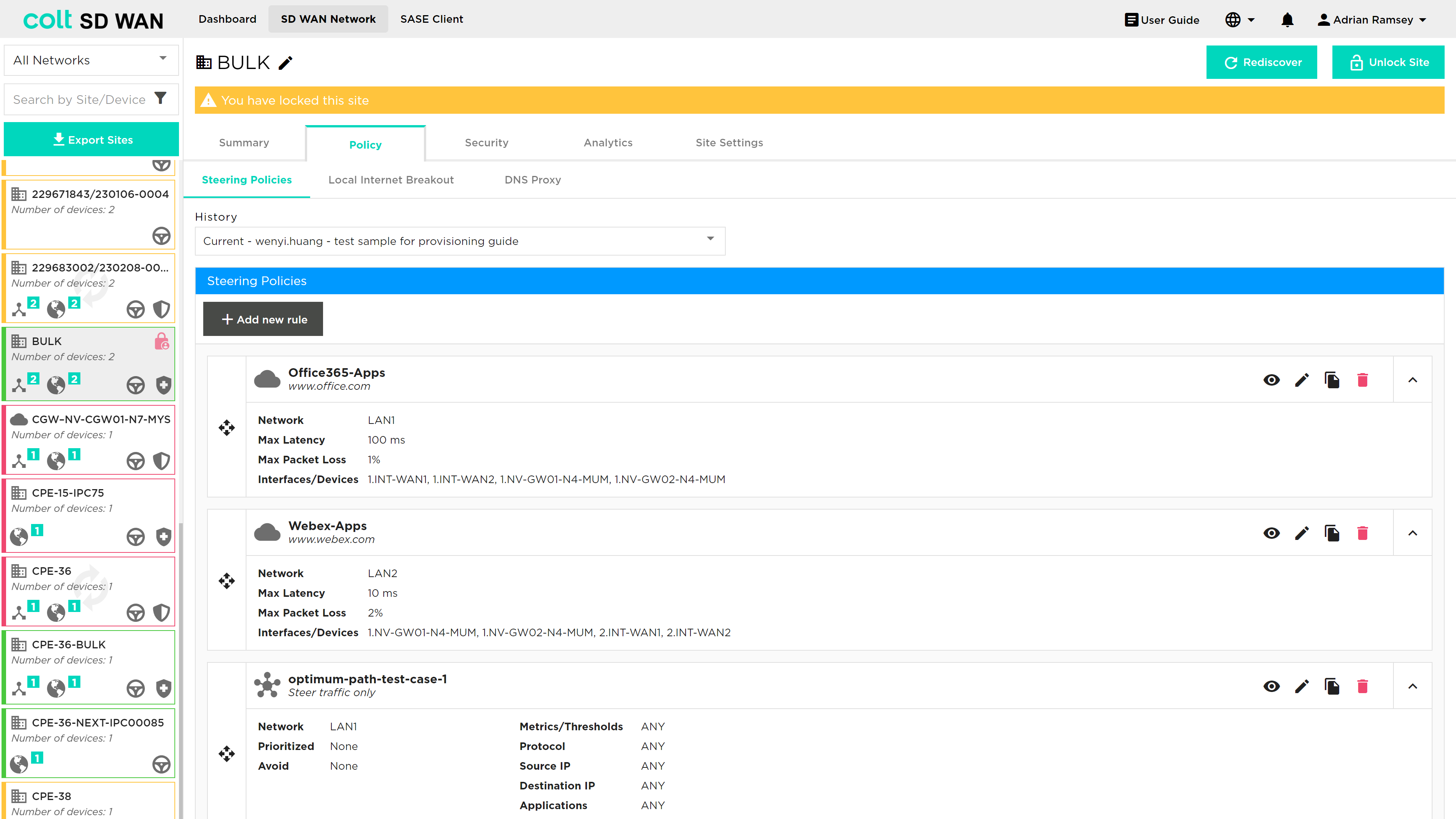
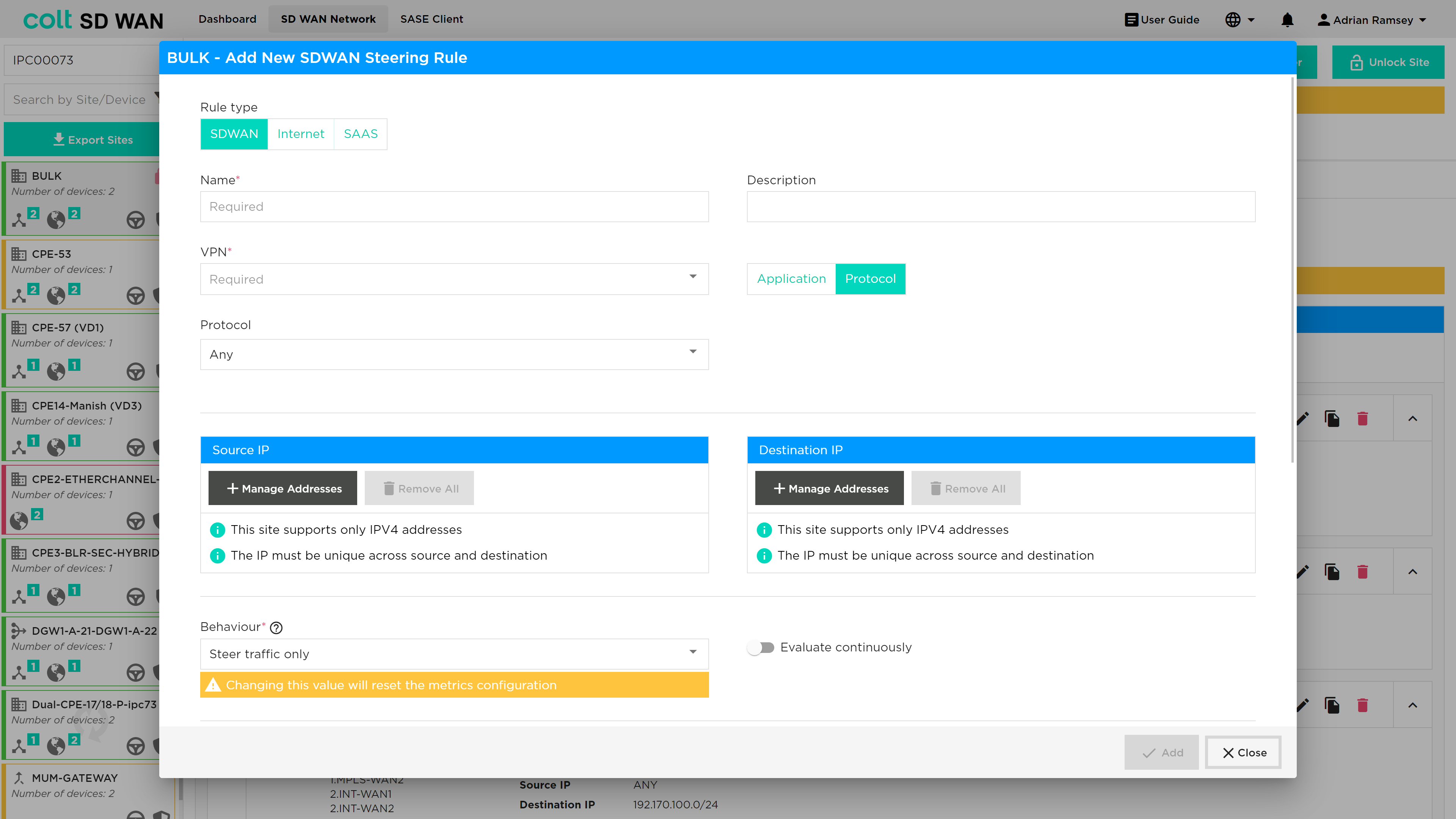
Once the user locks the site to enable editing, then a new rule can be added by pressing the '+ Add new rule' button. The user can then select 'SDWAN' at the top of the steering window as shown below:
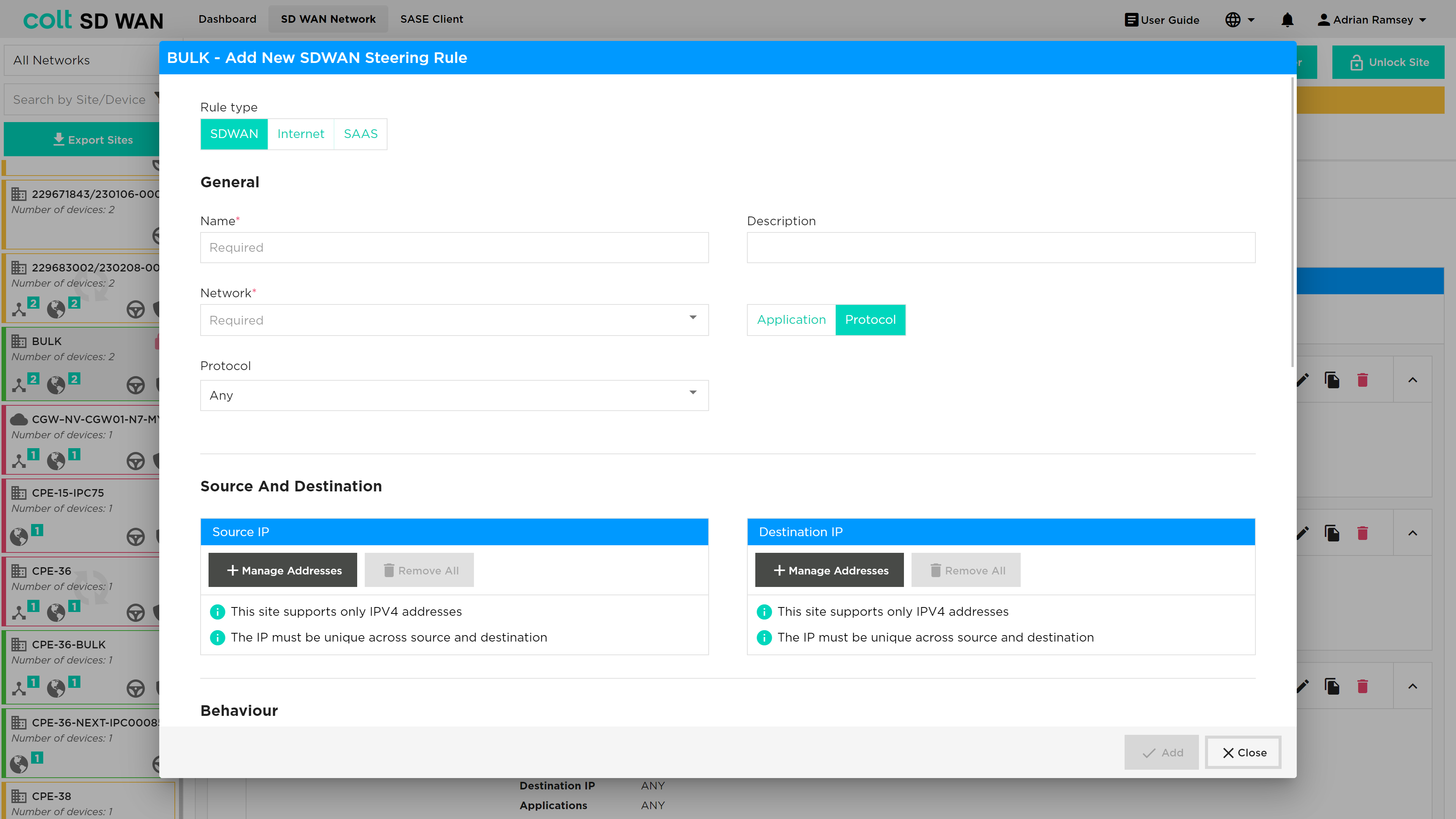
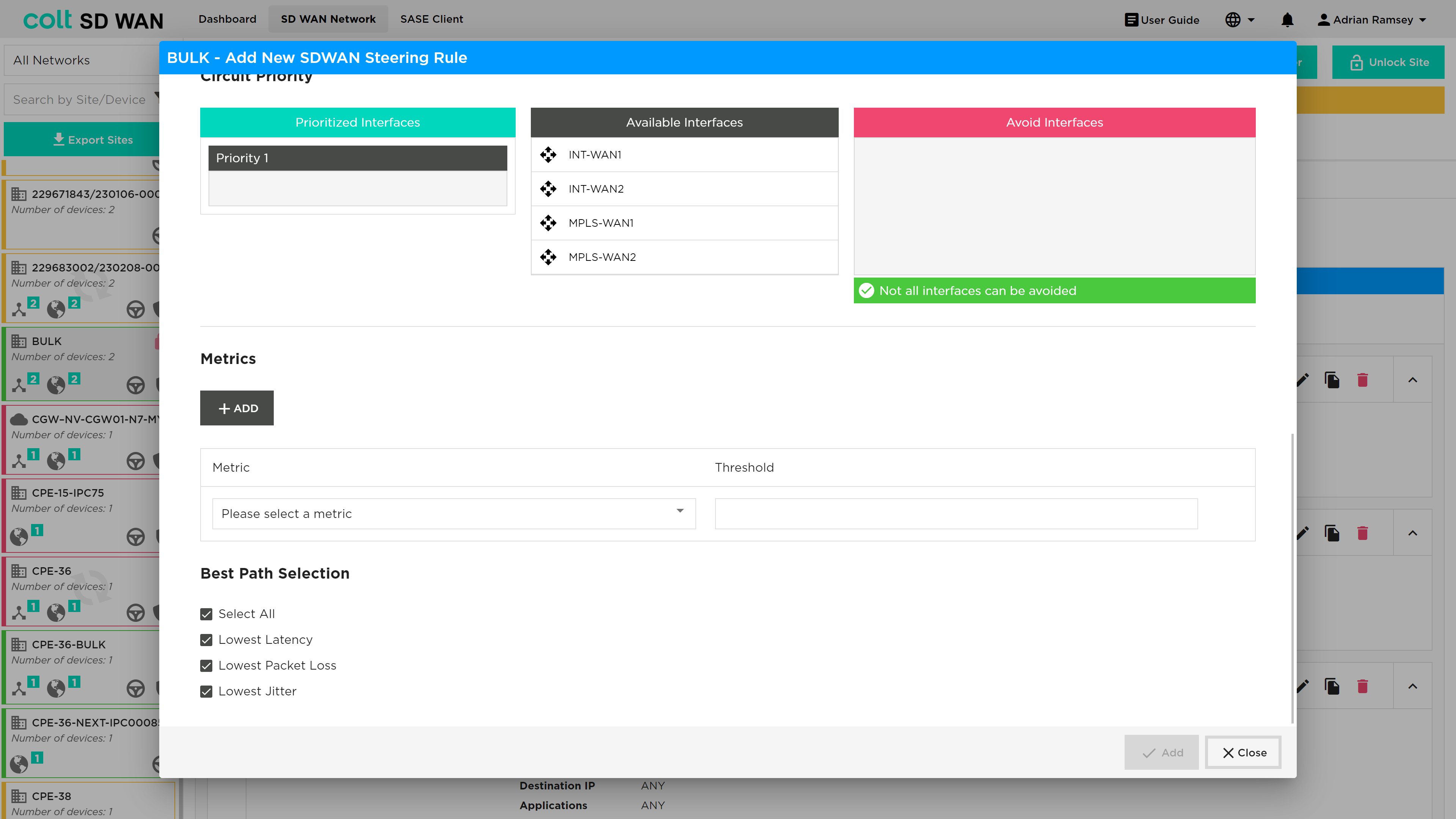
At the bottom of the 'Add New SDWAN Steering Rule' window the user is able to set the Best Path selection as shown below:
There are a variety of combination possibilities best path selections and using this capability with or without more deterministic steering rules. We will explain this below including the main example use cases, starting with the detail of the Dynamic Path Selection configuration parameters.
Explanation of new configuration parameters:
-
Best Path Selection (Optional, single choice): Button for activating the behaviour of Best Path Selection. If selected then the three lower metrics fields will appear on the panel as selected by default.
-
New three Metrics (Mandatory, Multiple choice): o Lowest Latency (Optional): To configure the best path based on the lowest latency. No Threshold value can be configured. o Lowest Packet Loss (Optional): To configure the best path based on the lowest packet Loss. No Threshold value can be configured. o Lowest Jitter (Optional): To configure the best path based on the lowest Jitter. No Threshold value can be configured.
As mentioned, in addition to this functionality for traffic selection, existing options that we provide for SD WAN traffic Steering Rules are still available. These are:
-
Configuration of different circuit priorities
-
Configuration of SLA thresholds for several metrics: Latency (ms), Jitter (ms), Packet loss (%), Transmit/Receive Bandwidth utilization (%)
-
Continuous evaluation of the traffic sessions that provides the traffic switching between difference paths, when the used path is no longer SLA compliant or there is a better option with <10% of difference
For implementation of Optimum path selection there are 4 use cases:
USE CASE 1: Best Path Only (Simple Case)
-
Site Type: Single CPE with MPLS and Internet WAN
-
Policy Rule: Match Selected Traffic, Enable best path for one or more metrics, no circuit priorities, no SLA thresholds
-
Normal Behaviour: Best path used, or both if performance difference is <10%.
USE CASE 2: Best Path with circuit priorities
-
Site Type: Dual CPE with MPLS, Internet and LTE WAN
-
Policy Rule: Match Selected Traffic, Enable best path for one or more metrics, MPLS and Internet Priority 1, LTE Priority 2, no SLA thresholds
-
Normal Behaviour: Best path amongst MPLS and Internet circuit used (or both if performance difference is <10%). LTE is unused
-
Failure 1 - MPLS path down: Internet path Used. LTE is unused
-
Failure 2 - Internet path down: MPLS path used. LTE is unused
-
Failure 3 - Both Internet and MPLS down: LTE path used
USE CASE 3: Best Path with SLA thresholds
-
Site Type: Dual CPE with MPLS, Internet1 and Internet2 WAN
-
Policy Rule: Match Selected Traffic, Enable best path for one or more metrics, no circuit priorities, SLA thresholds set (e.g. 100ms latency, 80ms jitter, 5% packet loss)
-
Normal Behaviour: Best path amongst MPLS, Internet1 and Internet2 WAN used (or multiple best paths if performance difference is <10%)
-
Failure 1 - SLA on MPLS path only exceeds thresholds e.g. latency >100ms: best path amongst Internet 1 and Internet 2 used, or both if performance difference is <10%.
-
Failure 2 – MPLS path down: Best path amongst Internet 1 and Internet 2 used, or both if performance difference is <10%.
USE CASE 4: Best Path with circuit priorities and SLA thresholds
-
Site Type: Dual CPE with MPLS, Internet1 and Internet2 WAN
-
Policy Rule: Match Selected Traffic, Enable Best path for one or more metrics, MPLS Priority 1, Internet1 and Internet2 Priority 2, SLA thresholds set (e.g. 100ms latency, 80ms jitter, 5% packet loss)
-
Normal Behaviour: MPLS path used
-
Failure 1 – SLA on MPLS path exceeds thresholds e.g. latency >100ms: best path amongst Internet 1 and Internet 2 used, or both if performance difference is <10%.
-
Failure 2 – MPLS path down: Best path amongst Internet 1 and Internet 2 used, or both if performance difference is <10%.
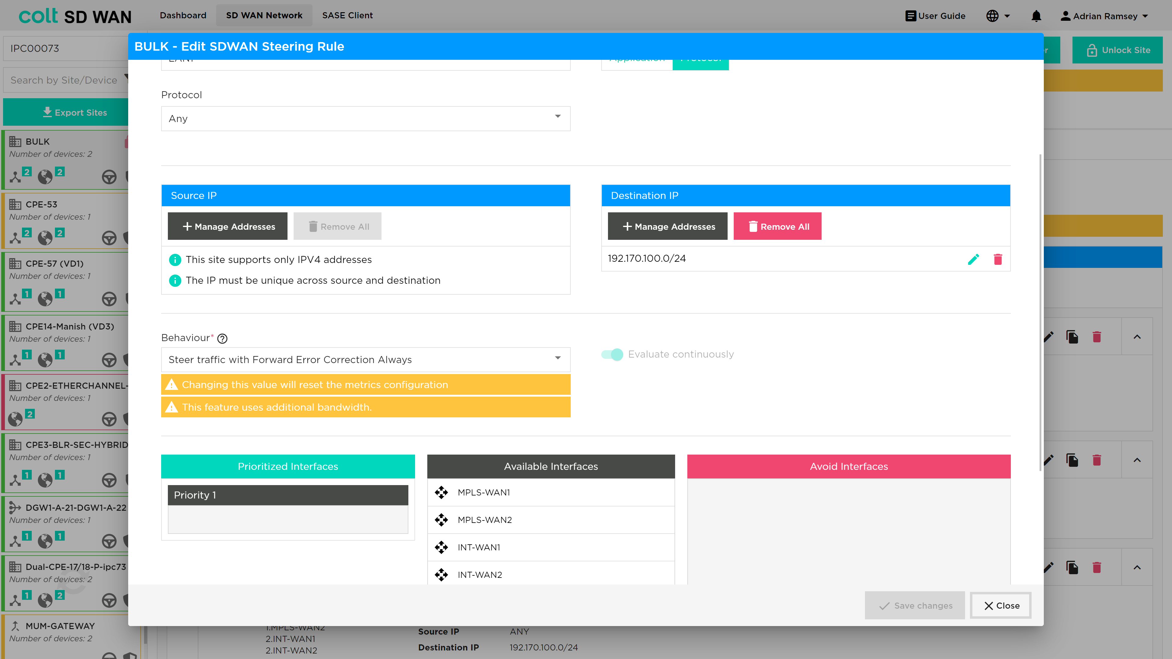
Traffic Optimization
|
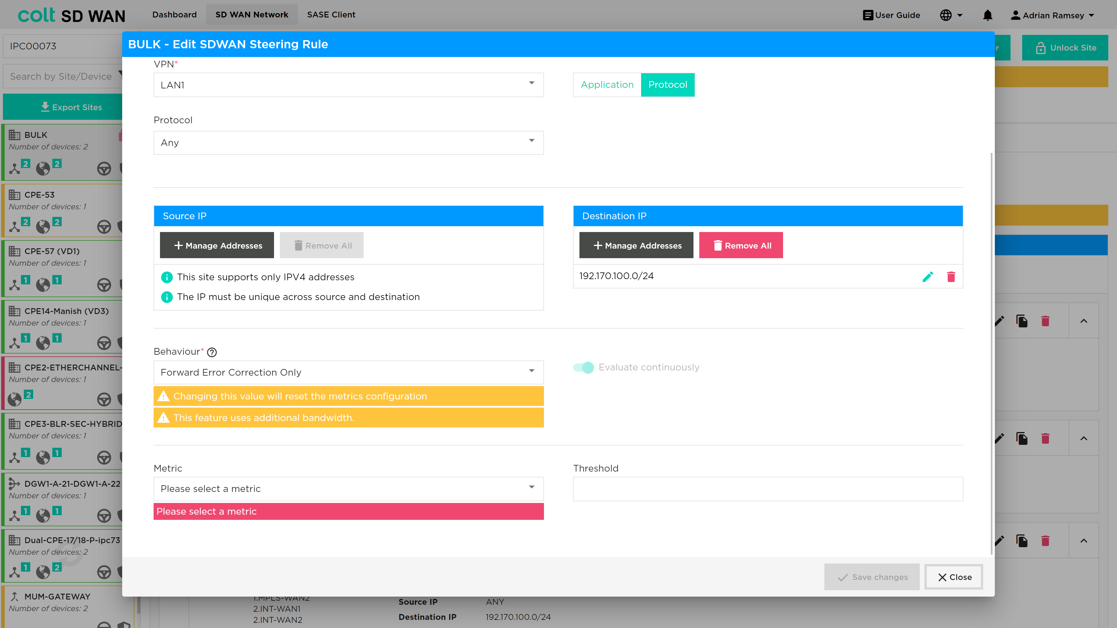
Traffic Optimization using FEC and Packet Replication requires a knowledge of the WAN Optimization. The inappropriate selection of these features can result in reduced performance of your SD WAN CPE and increased utilization of WAN links. Colt provides these services but does not provide a design recommendations or support decisions made by customers when using these features. FEC and Packet Replication policies apply to traffic originating on the LAN/DMZ and towards the SD WAN network only. |
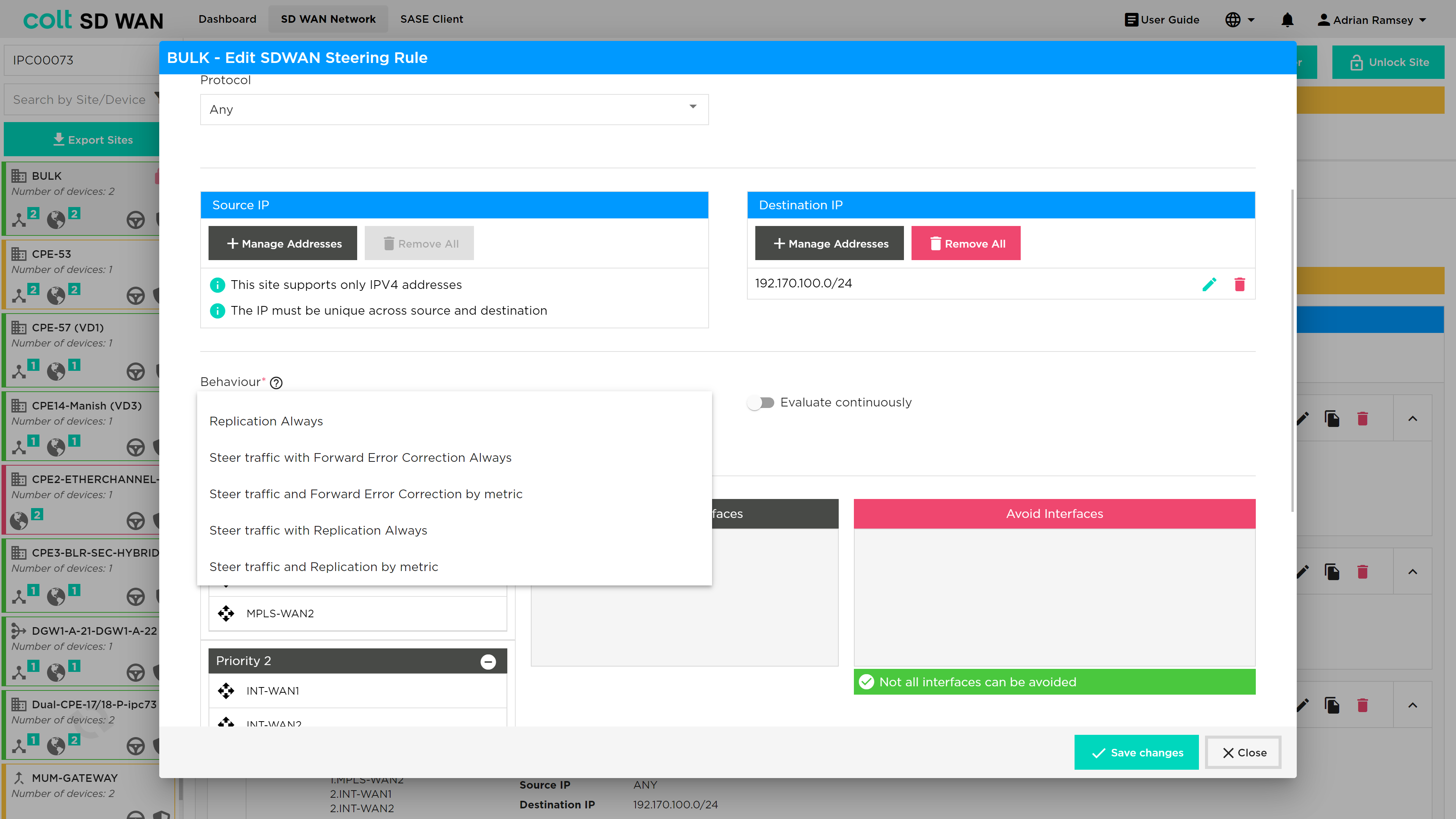
Traffic optimization uses FEC (Forward Error Correction) and Packet Replication combined with the option for traffic steering of specific applications with and without metrics. Below are short descriptions of FEC and Packet Replication for background information.
Traffic optimization provides an ability to enable the following services with and without traffic steering:
-
Forward Error Correction
-
Packet Replication
The basic setting allows customers to do the following:
-
Set FEC and Packet replication to be always on
-
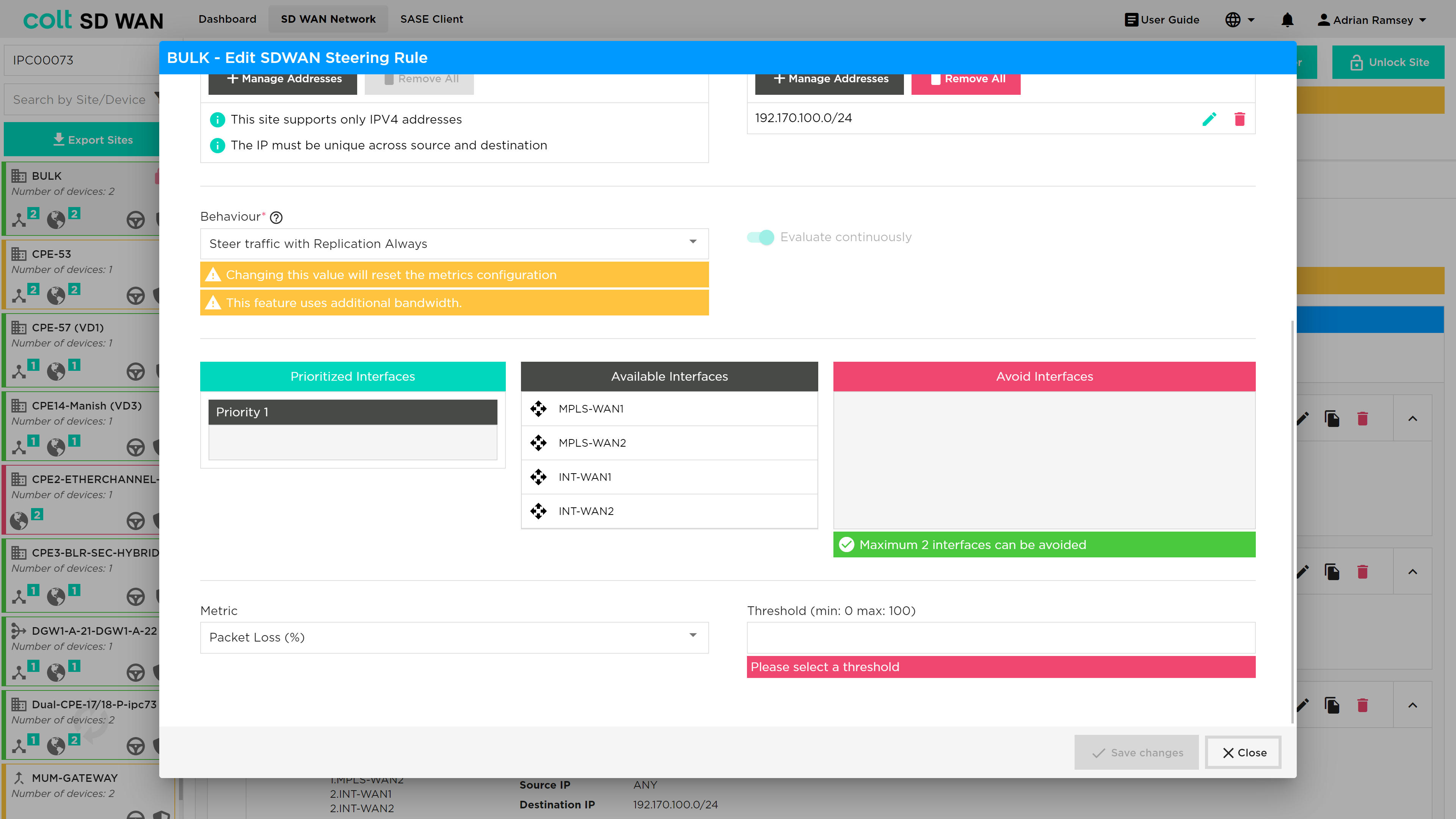
Enable FEC and Packet replication when a user defined Packet Loss threshold has been reached
-
Steer traffic with FEC and Packet replication from one link to another
-
Steer traffic with FEC and Packet replication from one link to another using the link priority list and packet loss metric
| When traffic steering and FEC/Packet replication is enabled, the order of action is that traffic steering will take priority. Then once traffic has been steered to the last WAN link in the priority order, traffic optimization will be enabled when packet loss is equal to the set threshold defined in that rule. |
A full list of the traffic steering and shaping combinations are shown in the Appendix under WAN Optimization rules.
Always enable FEC and Packet Replication:
Enable FEC or Packet Replication when the Packet Loss threshold has been reached:
Packet steering when FEC or Packet Replication is always on:
The Packet Loss metric allows you to set the % of packet loss by entering a specific value. This metric measures the percentage of lost packets in a network.
Traffic steering when FEC and Packet Replication is always on but no metric set:
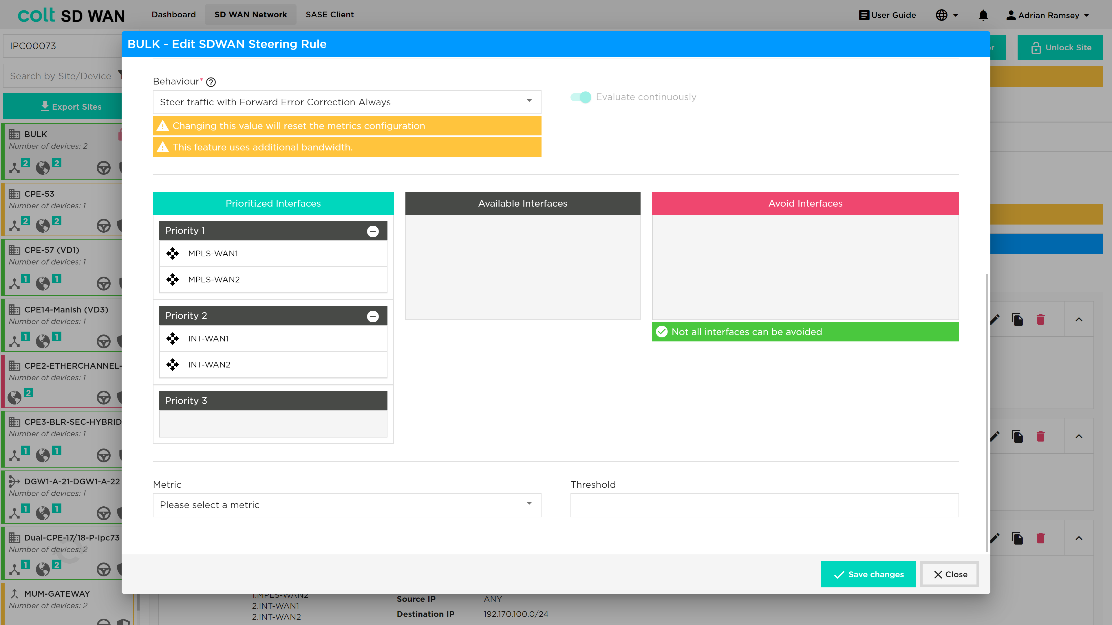
Traffic steering also allows the option to ‘avoid’ interfaces in the priority list. This is used to ensure traffic does not utilize WAN connection that don’t have the characteristics or bandwidth to support the underlying services.
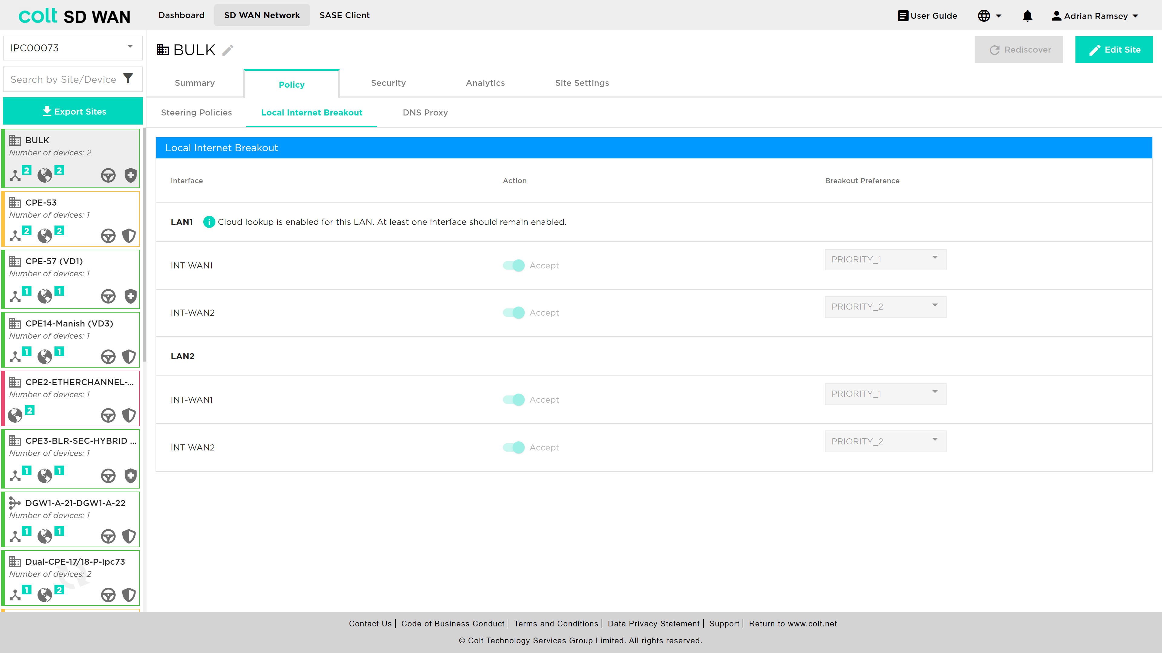
Local Internet Breakout
| This feature can only be used after respective firewall rules have been added from the Security tab of the branch device. |
As mentioned above, local internet breakout can be specified for each VRF/VPN. The default configuration for sites with multiple internet WAN connections is load sharing, where all local interfaces are set to the same priority. The list of Local WAN interfaces is provisioned at the time the site is implemented. It is possible to disable specific interfaces or modify the priority order for outbound traffic utilization. The process for chaning can be shown below.
| Customers with URL Filtering must maintain at least one active WAN connection to ensure cloud lookups can be made from that site. |
Central Internet Breakout
| This feature can only be used after respective firewall rules have been added from the Security tab of the gateway device. |
In addition to local Internet breakout, the Customer will have the option of selecting central internet breakout. There are 3 options for Customer dedicated Central Internet gateway:
-
Customer hosted (SD WAN site) Internet gateway
-
Colt hosted Internet gateway (no SDWAN hub or MPLS NNI)
-
Dedicated SD WAN Gateway (SD WAN Hub/MPLS NNI and Internet gateway)
-
Branch SD WAN Gateway (SD WAN Hub/MPLS NNI and Internet gateway)
For SDWAN sites enabled with Local Internet Breakout, Internet traffic will be routed over local Internet WAN uplink. In case of LIB failure, traffic will be routed route over central internet gateway.
In case of Internet link failure, Internet traffic from SDWAN branch sites to Customer Internet gateway will be over SDWAN overlay on MPLS from branch to gateway for hybrid sites.
For MPLS only sites, Internet will be accessible through Internet gateway sites.
A customer will have Central Internet Breakout configured at a network level as opposed to on a site level. With Central Internet Breakout the customer no longer requires any particular site to have a local Internet connection to break out to the Internet. Steering is configured on the Internet Traffic Steering tab as shown below.
Internet Traffic Steering
| Where previously SD WAN Steering rules took precedence over Internet Steering rules, this is no longer the case and the order of processing will be as the user selects and is displayed in the site summary of all rules. |
Internet Break out options have been introduced to allow SDWAN Portal users to do the following on a per site bases:
-
Enable Local Internet Breakout for outbound (LAN to Internet)
-
Enable Central Internet Breakout for outbound (LAN to Internet)
-
For each elect additional Internet Breakout gateways for internet outbound traffic
-
Create application policies to steer internet traffic to priority list of Internet or Internet gateways
Internet Breakout is provided through the Internet WAN interfaces. By default, the customer will have at least one Internet interface enabled and set with a priority of 1 for local internet services, including cloud lookup, as shown below:
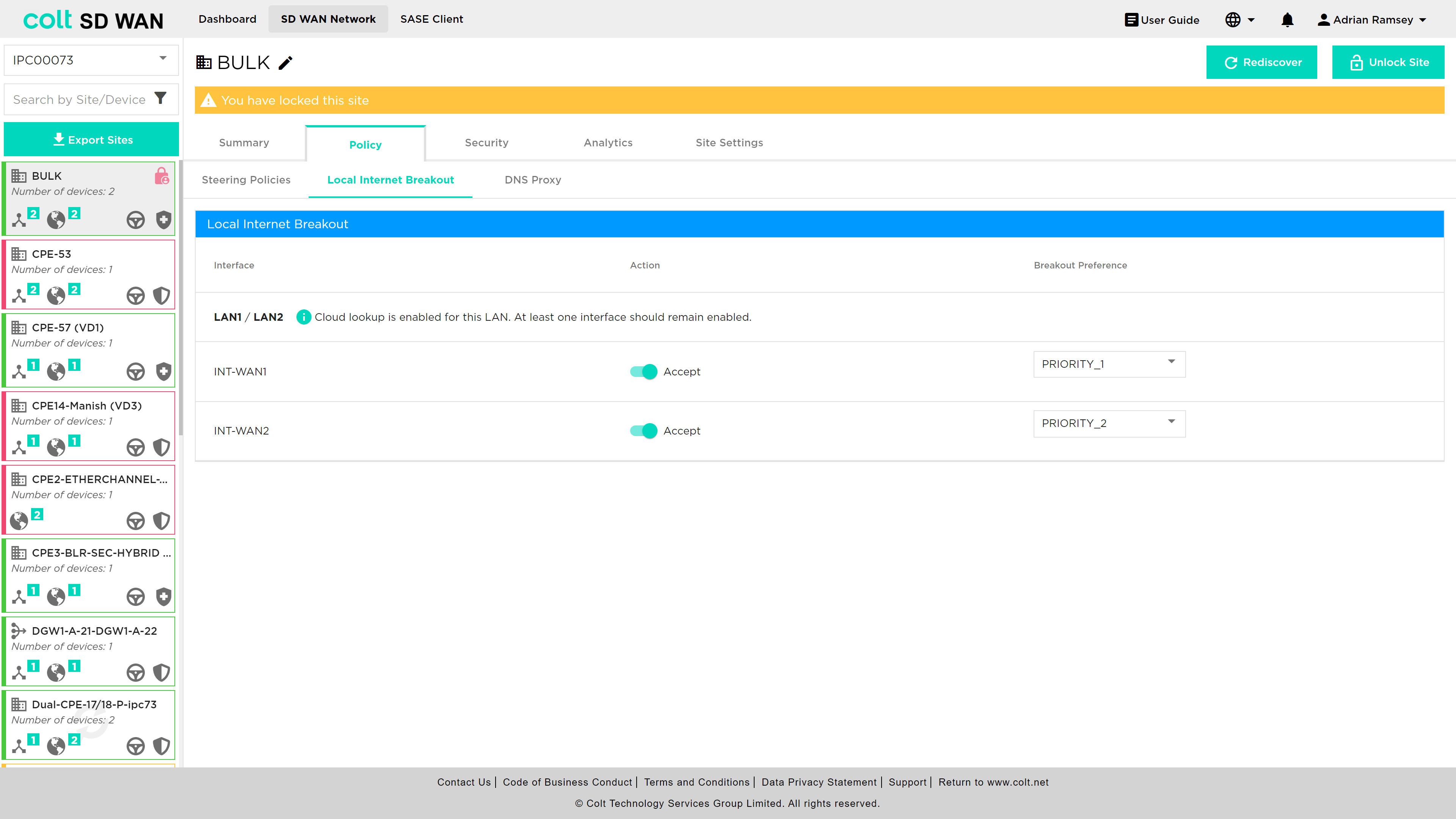
By default those customers who have multiple Internet WAN connections on the same site will have all enabled for local internet in Active/Active configuration for outbound traffic. A customer can choose to change to a ordered list of breakouts by changing the priority assigned to each.
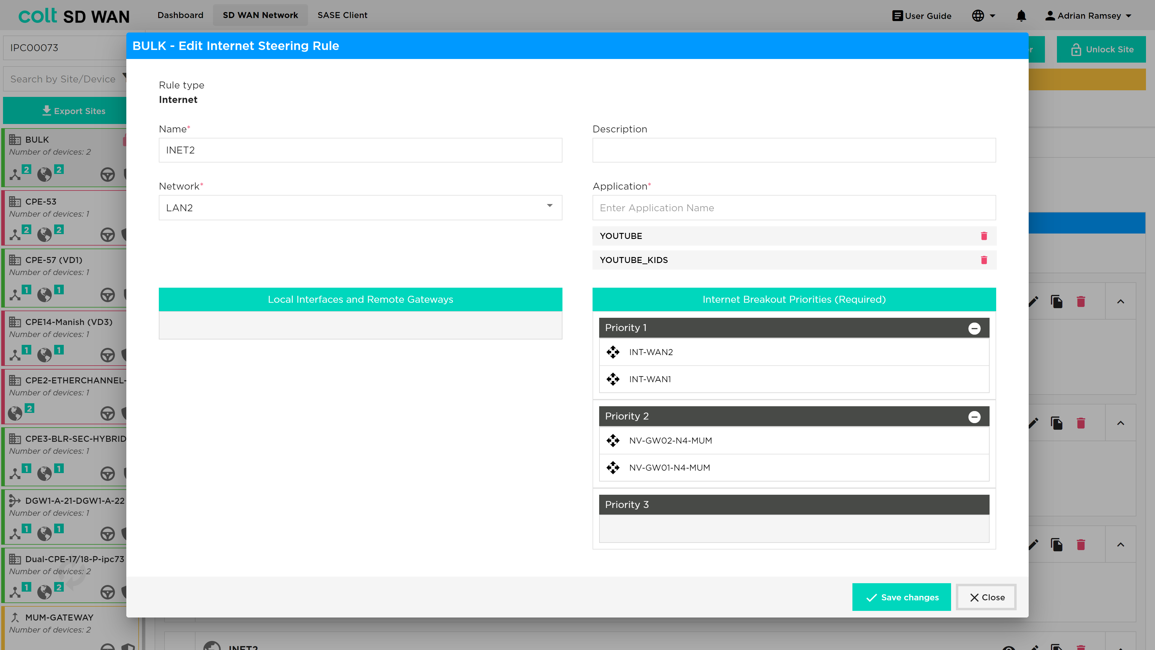
Internet Traffic Steering provides the ability to view, edit, add and delete application based traffic steering rules per site. New rules can be added as shown below:
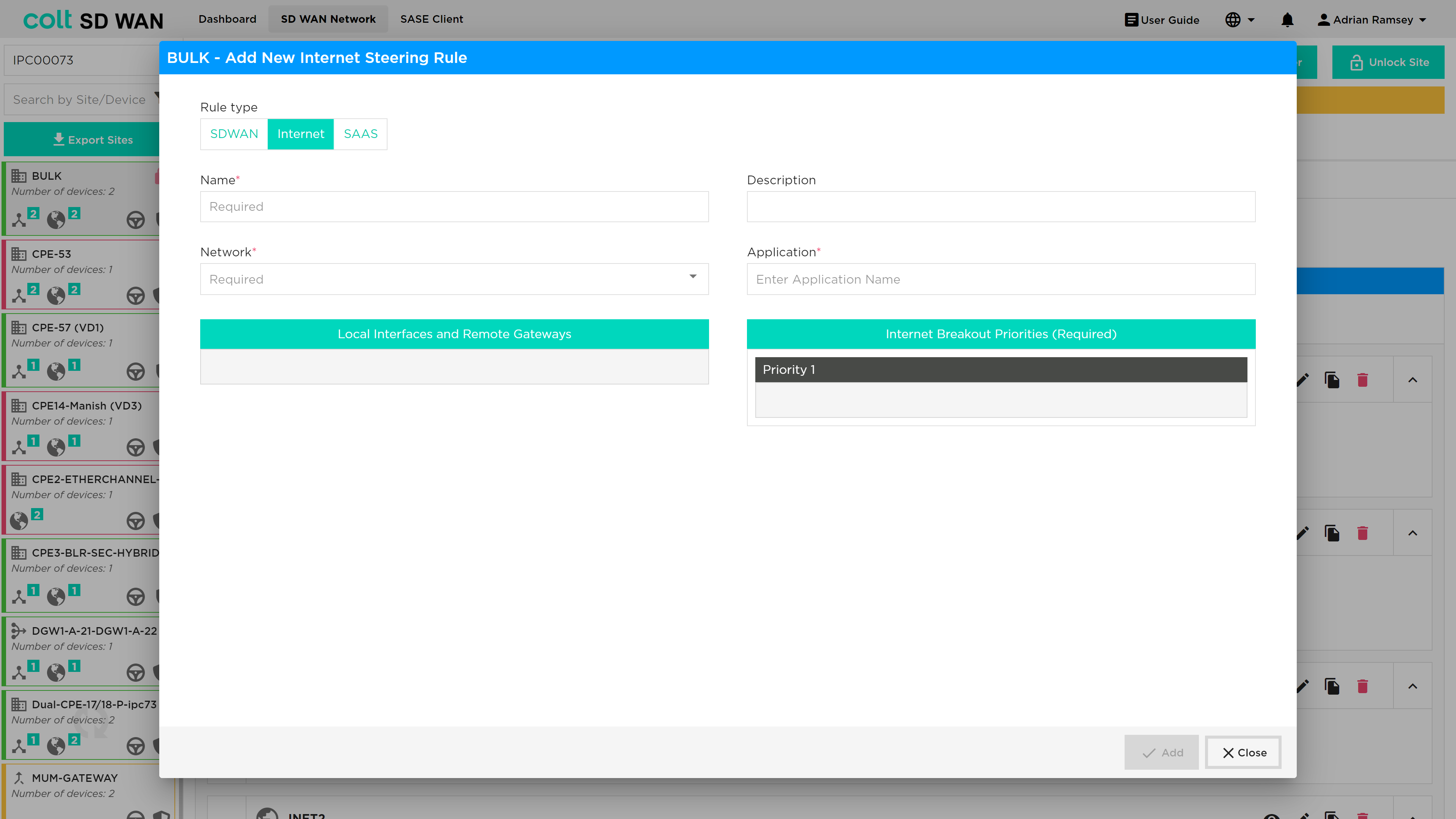
The options allow selection of the application by VPN and the creation of a ordered priority list for internet breakout traffic only. The list of available outbound interfaces will be Central Internet Breakout Gateway or local internet interface at that site.
| Inbound Internet traffic will be managed per interface, i.e. the primary link will be used or if DNS or specific applications use an IP address assigned to a subnet on another Internet WAN link then specific DNAT/SNAT policies and FW rules need to be created. These can be created per device, which includes the Branch and Central Internet Gateways. |
A list of gateways that are linked to each branch site can be viewed from the Device page.
See below the dialogue box for adding a new internet traffic steering rule:
List view of internet traffic steering rules:
SaaS Optimization & DNS Proxy
DNS Proxy
| This feature provides the customer the ability to configure multiple DNS profiles for capturing queries from the LAN for sending to the selected DNS servers. One example of use of this feature is split DNS by having two DNS profiles. One rule for redirection of queries to internal domains through an enterprise corporate DNS and second to redirect the rest of the DNS queries to external or Global DNS servers. |
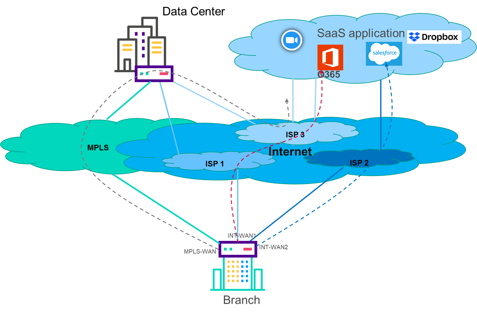
A DNS proxy profile is used to provide split DNS functionality. Typically, the proxy is configured to forward all enterprise internal names to a DNS server behind a HQ site, and to forward all external domain names to a public DNS server such as Google DNS or Open DNS. Now a DNS proxy profile can set the “honour-pbf” flag to true to indicate that SD WAN rules should be looked up to determine the path, on which to send the DNS query. For this to work, a DNS resolver needs to be available for each path that pbf can send the traffic on.
The DNS query that happens at the beginning of a web transaction is steered independently. This may result in sub-optimal DNS resolution. For example, consider a use case where salesforce traffic must use local breakout over either LBO1 or LBO2. It is possible that the Versa DNS proxy module independently steers the DNS query over local wan circuit LBO1, and PBF module steers the subsequent HTTP session(s) over either LBO1 or LBO2. Enabling Strict DNS path affinity helps pinning the subsequent HTTP/HTTPS sessions from the end client over same path DNS query resolved. DNS Proxy with “honour-pbf” enabled redirects the DNS query for selective domains, for example Office365, Salesforce & Dropbox and lookup the SD WAN policy rule defined for these applications and determine the path to send the DNS query.
This is illustrated in the diagram below:
The DNS Proxy tab can be found underneath the Policy tab and a specific site screen as shown below.
Once the site has been unlocked then the user can select the 'Add DNS Profile' button and the following screen opens.
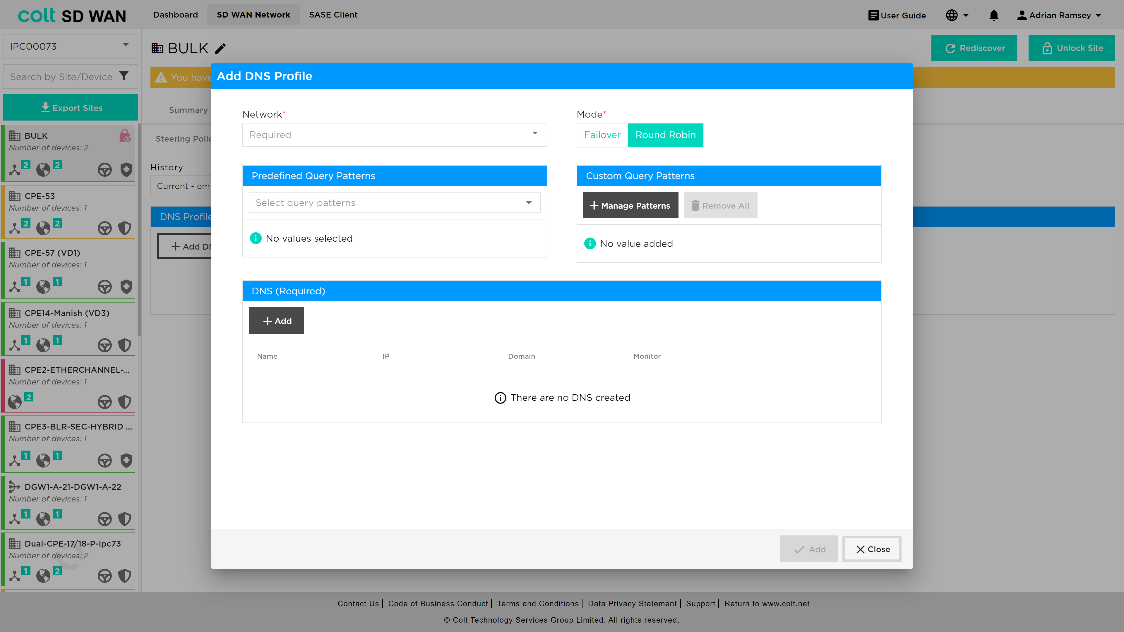
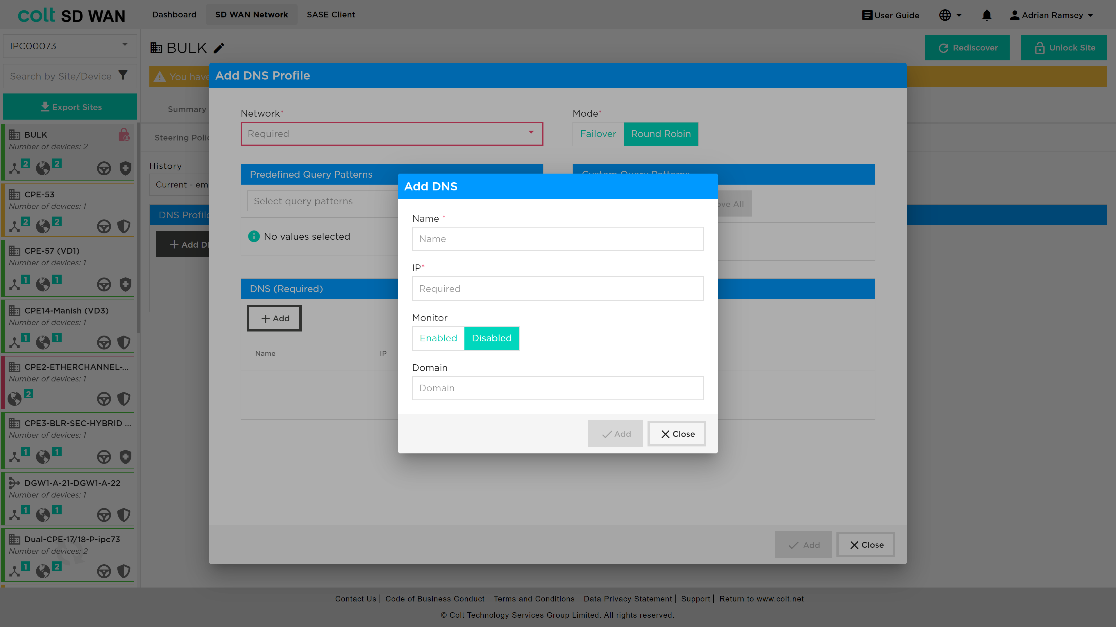
Within this screen the customer needs to add DNS details under the DNS (Required) section. once the user presses the +Add button the following screen opens:
An explanation of the parameters required from the user:
-
Network (Mandatory, single choice): Avaiable associated LAN Networks will be available for single choice.
-
Mode (Mandatory, single choice): Selection of DNS behavior mode if Failover or Round Robin for all DNS configured on the policy.
-
DNS – Name (Mandatory, customer input): Name given by the customer.
-
DNS – IP address (Mandatory, customer input): IP address for the DNS Name mentioned above.
-
DNS query pattern (Optional, Customer input): Customer can provide the DNS pattern for the matching criteria of the DNS queries to be resolved by the DNS’s configured on the associated profile.
SaaS Optimization
|
This feature is designed to improve the current Internet traffic steering rules by providing path selection based on the best performance to specific SaaS Applications. So in comparison with the current Internet traffic steering it is not possible to make a path selection based on the defined SLAs. In order to achieve the internet traffic steering SLA driven policy, we are introducing several mechanisms:
|
In a typical SDWAN deployment, there are multiple WAN-links/paths to reach a given Application and it is important to choose the best path based on metrics collected by an active monitor to improve the overall user experience. While this capability is not available for Internet based applications, using Active SaaS monitor, path selection for selective SaaS applications can be influenced to use local-breakout or remote-breakout to achieve better application performance.
|
DNS-Proxy MUST be configured to enable SaaS steering rules to function properly. In addition: • DNS settings for SaaS applications are able to make use of user selectable predefined DNS patterns in conjunction with customized patterns added seperately • It is highly recommended to configure Global DNS servers for SaaS applications to provide better DNS resolutions |
In order to configure SaaS steering rules it is required to have one of these combinations: • One INT-WAN Link with LIB enabled and CIB from Gateway(s) • Two INT-WAN Links with LIB enabled • CIB on Gateway(s), only in case of the customer wanting to use them as next-hop. So the Gateway must have Next-Gen Firewall enabled for the relevant customer ORG. • On the Gateway(s) SaaS-Application Monitor will already be created for each SaaS-App on the Colt ORG: <SAAS_APP_NAME> and new QoS rules to allow that performance statistic traffic. On Dedicated Gateways this configuration must be configured on the Customer ORG.
| As standard the LAN traffic to SaaS-Apps must be allowed from FW-Rules managed by the customer on the portal for the relevant branch site and Gateway if selected. |
To add a new SaaS steering rule, the user nagivates to Policy → Steering Policies and after unlocking the site presses the '+ Add new rule' button. The following screen opens and the user should select 'SAAS' from the rule type selection at the top of the window.

An explanation of the parameters required from the user:
-
SaaS-Application (Mandatory, single choice): there will be approximately 22 SaaS-Applications available for the Customer to select from.
-
Network (Mandatory, single choice): Selection of the VPN (LAN-VRF) that will be applicable for the SaaS-Policy.
-
Maximum Latency (ms) (Mandatory, customer input value): Integer value in for maximum latency in millisecond of SLA associated to the next-hop defined by customer from 1 to 1000 ms.
-
Maximum packet loss (%) (Mandatory, customer input value): Integer or decimal value for maximum packet loss in percentage of SLA associated to the next-hop defined by customer by customer from 0.01 to 100%.
-
Available INT Transports (Mandatory, multiple choice for drag and drop): All the Internet transports from branch site will be visible at the box to drag and drop to the corresponding priority selected (1-3) by customer.
-
Available Gateways (Optional, multiple choice for drag and drop): All the Gateways available (Only with CIB enabled) from branch site will be visible at the box to drag and drop to the corresponding priority selected (1-3) by customer.
-
SLA Next-hops (Mandatory, multiple choice): in the boxes (Priority 1-3) the items from “Available INT Transport” and from “Available Gateways” will be moved based on the customer preference.
IP QoS Management
IP QoS Management has two aspects to the feature:
-
IP Flow assignment of DSCP value by match of IP address and Ports
-
Application of DSCP per application session
The basic IP QoS configuration allows Colt’s traffic class (Premium, Business 1, Business 2, Business 3) to be forwarding class that matches the IP VPN QoS policy. Application QoS provides session based QoS policy that include the IP Flow policies.
The feature is part of Policy or traffic steering menu options and a sub-menu is available as shown below where IP QoS policies can be viewed, edited, duplicated and set in priority order. The SDWAN service has 4 predefined forwarding classes: Premium, Business 1, Business 2 and Business 3. IP DSCP values are mapped to each class. In addition, each class has a fixed number of queues, queue depth and guaranteed transmit which are not configurable.
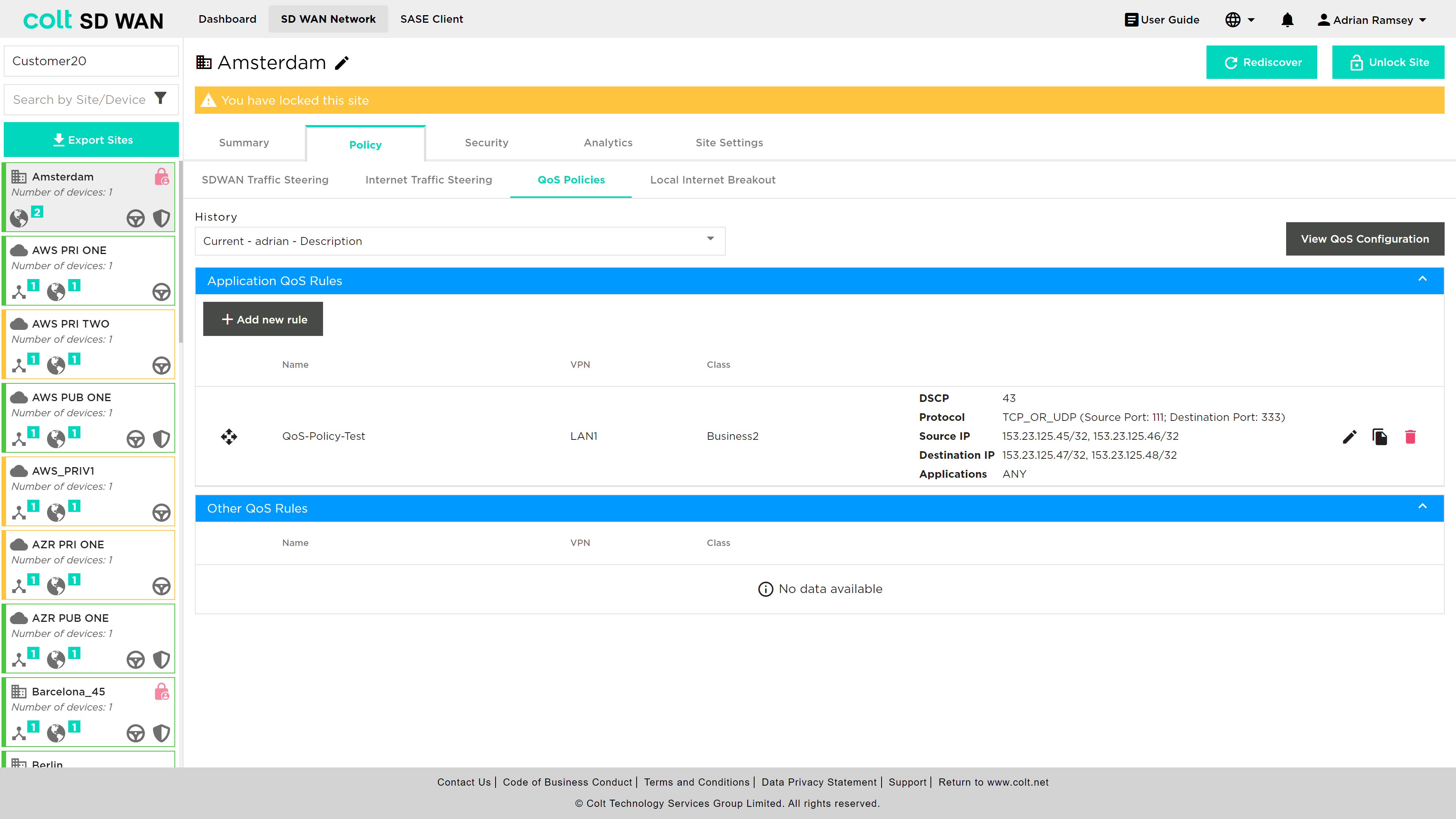
There is View QoS configuration which allows the view of the forwarding class configuration, including the DSCP assignment to each class, associated queues, guaranted bandwidth allocation and guaranteed transmit. The view shows the following:
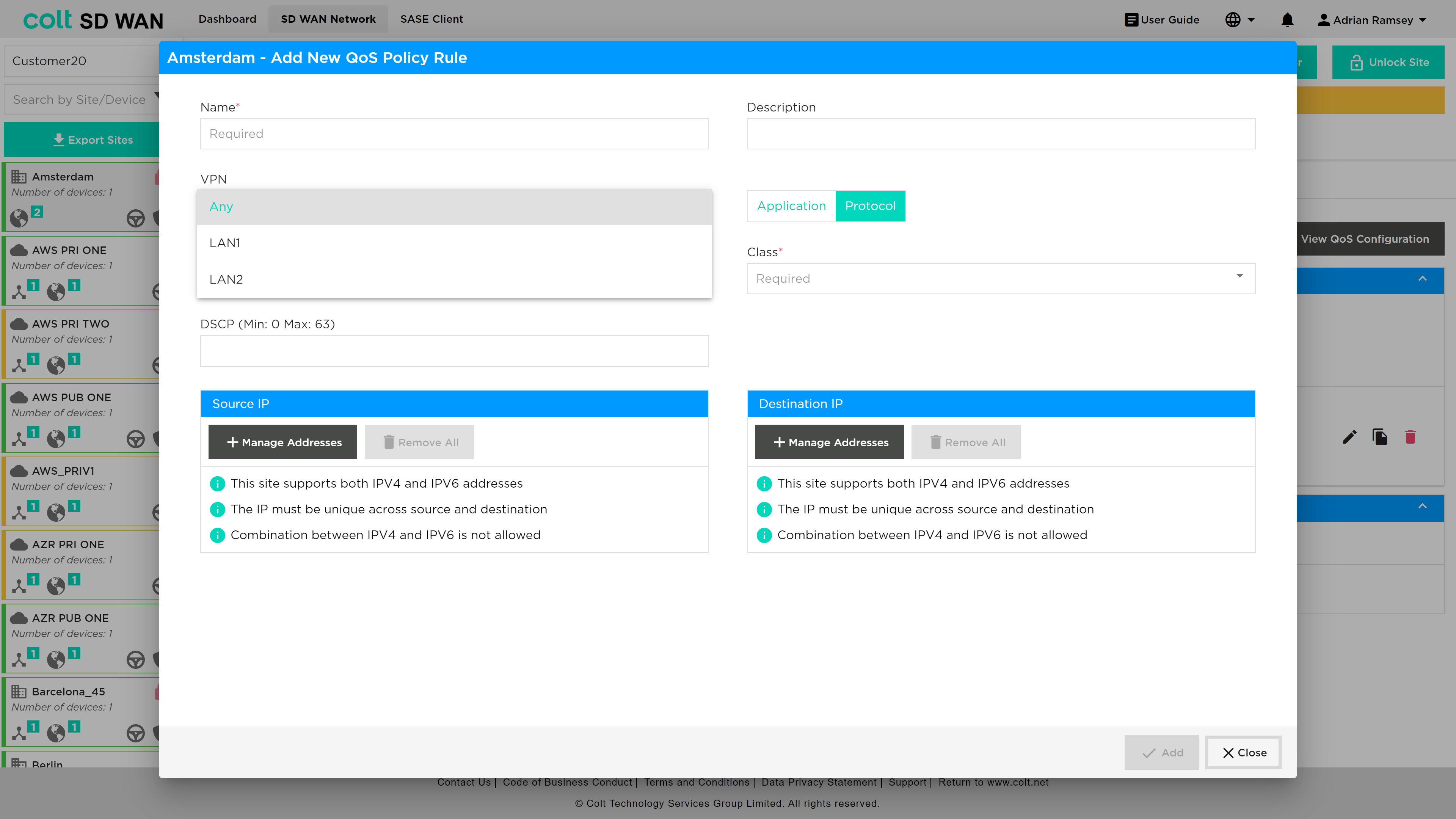
The process to add or edit a rule uses the same screens and parameters. To add a new rule, select the “Add New rule” button. The rule can be created with the following options:
-
VPN
-
Application
-
Source destination IP address combinations
-
-
Protocol
-
IP address (source & destination combinations)
-
Port number or ranges (source & destination combinations)
-
-
Class of Service
-
DSCP Value
The App QoS allows mapping per application session for IP QoS parameters to be applied to a specifc VPN or LAN VRF (needs high degree of expertise) or to apply to “Any” interface as that site. In the event the customer QoS profile mathes the Colt IP VPN profile no additional QoS policy are needed.
These IP QoS rules can be bulk copied using the Bulk Copy feature, see section here . In addition to Bulk copy the Command line console options now include snapshot views of the IP QoS class and queues, for more information see here.
In addition the Device page has an icon for each CPE that shows the command line output for:
-
QoS Policies
-
App QoS Policies
-
QoS Mapping
Also, the analytics data has IP QoS interface Analytics, see here
Internet Egress QoS
Internet Egress is a new non-chargeable feature that allows the user to apply Quality of Service (QoS) on the egress (outgoing) traffic of Internet based links of the SDWAN CPE. In the past, QoS capabilities were limited to MPLS networks, providing priority queuing and traffic management exclusively for that type of connection. However, with this recent enhancement, the QoS functionality has been extended to include Internet underlays as well. This means that the user can now apply priority queuing and traffic shaping on Internet connections, allowing for control and prioritization of data traffic. In order to set up Internet Egress QoS, the user´s CPE should have at least one Internet uplink and the configurations listed below:
-
QoS Profiles (Premium, Business 1/2/3, default - customer input)
-
Drop Profiles
-
Schedulers (customer input)
-
Scheduler Maps
-
Associated Internet Uplink(s) (customer input)
-
Classification Rules/Application QoS Rules (customer input)
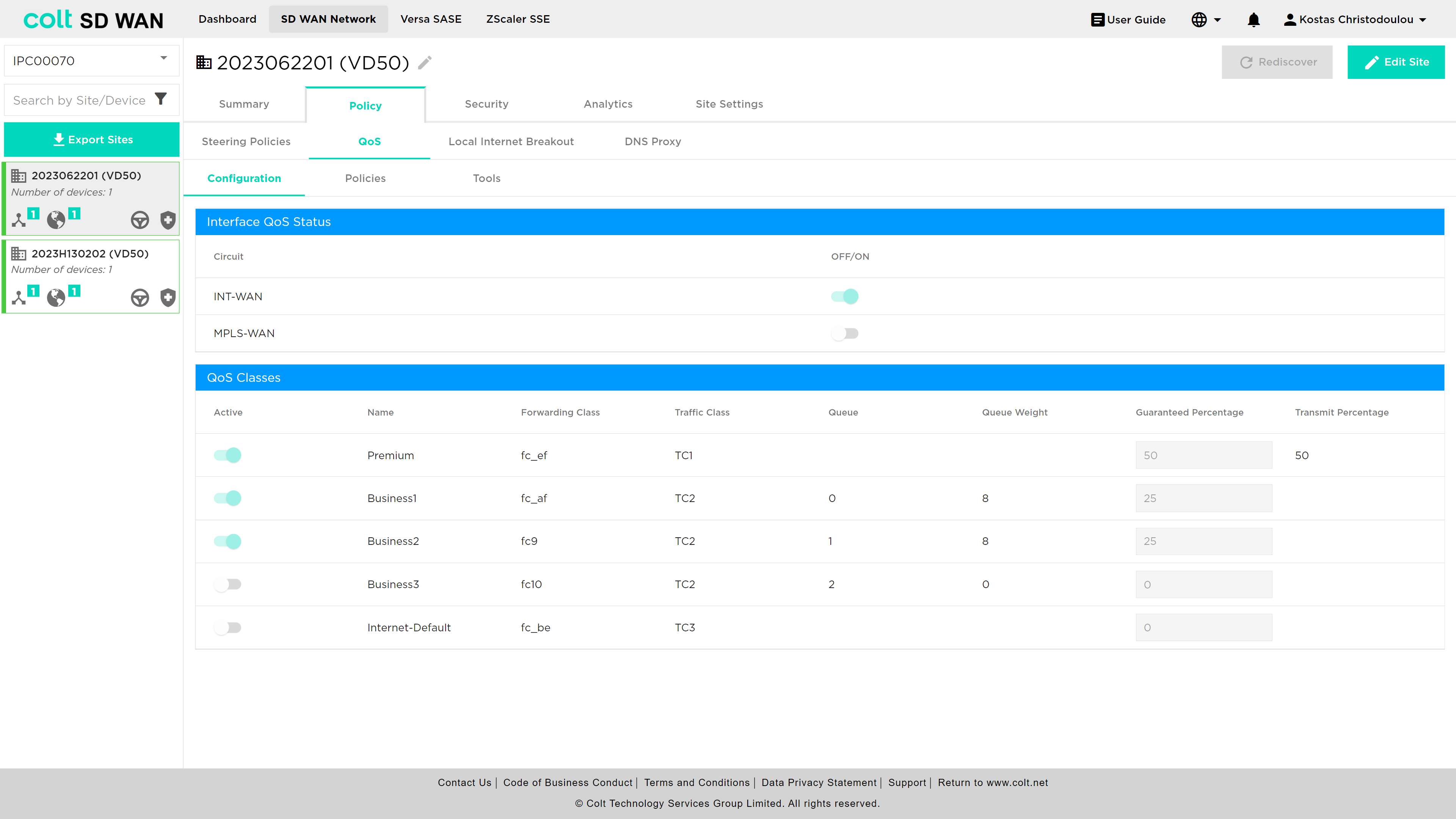
It is also important to note that the actual configuration impacts the SDWAN CPE and overlay only. Additionally, QoS on Internet links can be configured on the CPE for On-Net, OLO and Bring Your Own links (BYO). Internet Egress QoS, like MPLS QoS, allows traffic classes to be mapped as forwarding classes, effectively ensuring that critical applications or services receive the necessary bandwidth and priority, while less important or non-essential traffic is appropriately managed. The mapping is done as shown below:
| Traffic Class | Forwarding Class | Traffic Class | Traffic Type | Queue | Loss Priority | DSCP Rewrite | Dot1P Rewrite |
|---|---|---|---|---|---|---|---|
Premium |
Forwarding Class 4 |
TC1 |
Highest Priority - Real-time voice and video (eg. MS Teams, Zoom) |
- |
Low |
No |
No |
Business1 |
Forwarding Class 8 |
TC2 |
High Priority - ERP systems, database transactions |
0 |
High |
No |
No |
Business2 |
Forwarding Class 9 |
TC2 |
High Priority - Important business applications, financials transactions |
1 |
High |
No |
No |
Business3 |
Forwarding Class 10 |
TC2 |
High Priority - Critical business applications, real-time data trading |
2 |
High |
No |
No |
Internet-Default |
Forwarding Class 12 |
TC3 |
Medium Priortiy - Web browsing, software updates |
- |
High |
No |
No |
For enabling Internet Egress QoS for the first time, the user needs to navigate to the Policy page and click on the QoS tab.
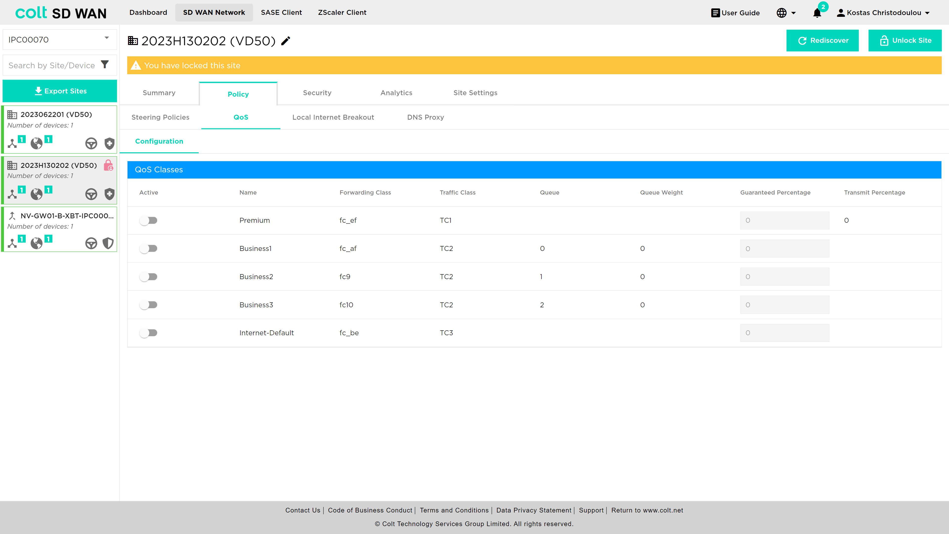
Then the user needs to activate the QoS classes they want and together with the activation of the classes, a new table will appear and the Interface QoS Status can be switched on/off.
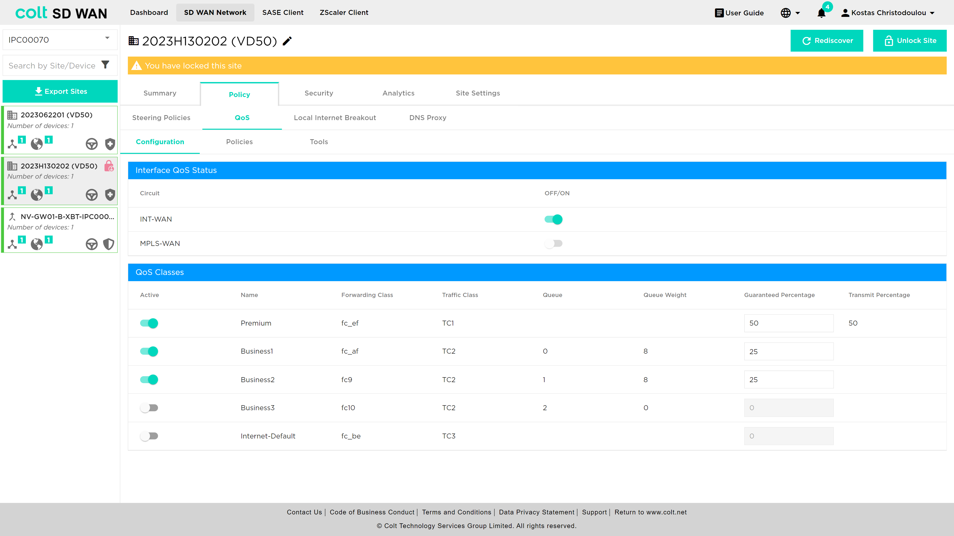
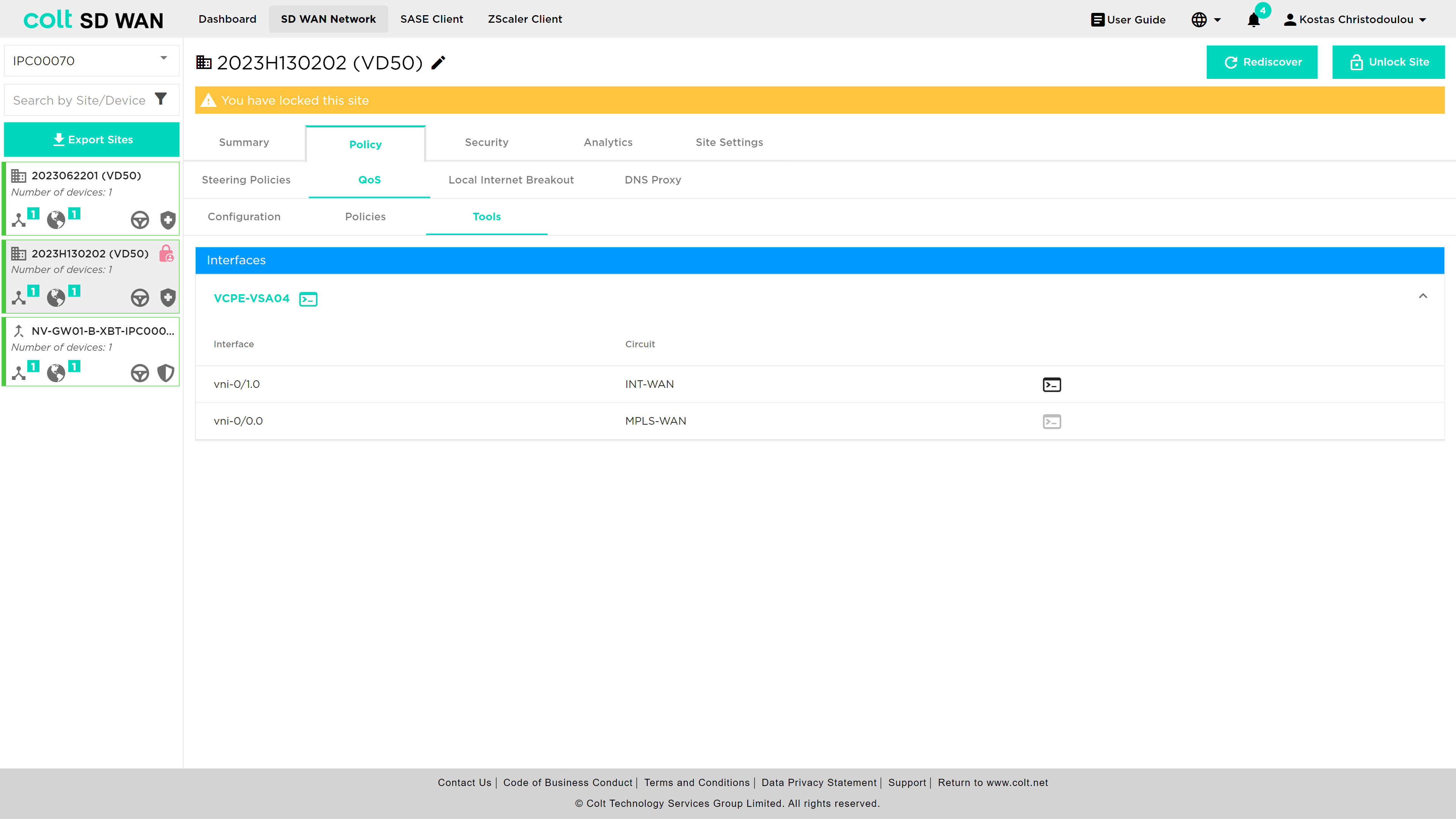
In addition, the execution of QoS commands has now been moved from the Summary page to the Tools section under QoS.
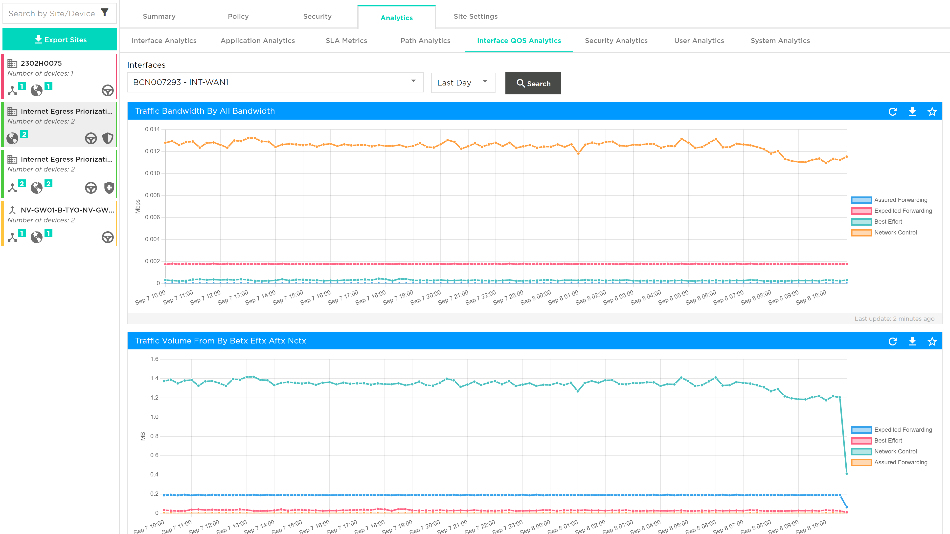
Last, the display of Internet WAN QoS Logging will be in the Analytics tab, under Interface QoS Analytics. See picture below:
The following Use Cases, describe the scenarios where Internet Egress QoS can be applied:
Use Case 1: QoS Internet Site only Scenario 1: If at least one Internet uplink exists, the customer can configure QoS on Internet Egress. The necessary configurations/steps 1-6 are mentioned above. Scenario 2: If there are more than one Internet uplinks, the user can configure QoS on all available uplinks separately.
Use Case 2: QoS Hybrid Site Scenario 1: If there are MPLS and Internet uplinks, but no QoS enabled, the customer can configure the Internet QoS only, for MPLS configuration Colt SD need to configure. Scenario 2: If there are MPLS and Internet uplinks and QoS is enabled on MPLS, then the internet uplink will inherit the QoS attributes of the MPLS link, after enabling Internet QoS. Scenario 3: If there is a hybrid site with no QoS configured, the user will be able to configure Internet QoS only.
Security
The following section covers all security services provided by the next generation firewall. These are available as submenus under the main “Security” menu in the portal as shown below. The options are as follows:
-
Firewall (IP, port and application access control and URL Filtering)
-
Security Profiles – Antivirus, URL Filtering, IPS Vulnerability, IP Filtering
-
NAT (Static and Destination NAT)
-
Decryption
-
SSL Certificates
-
DDoS (IP based DoS policy creation)
-
Secure log forwarding
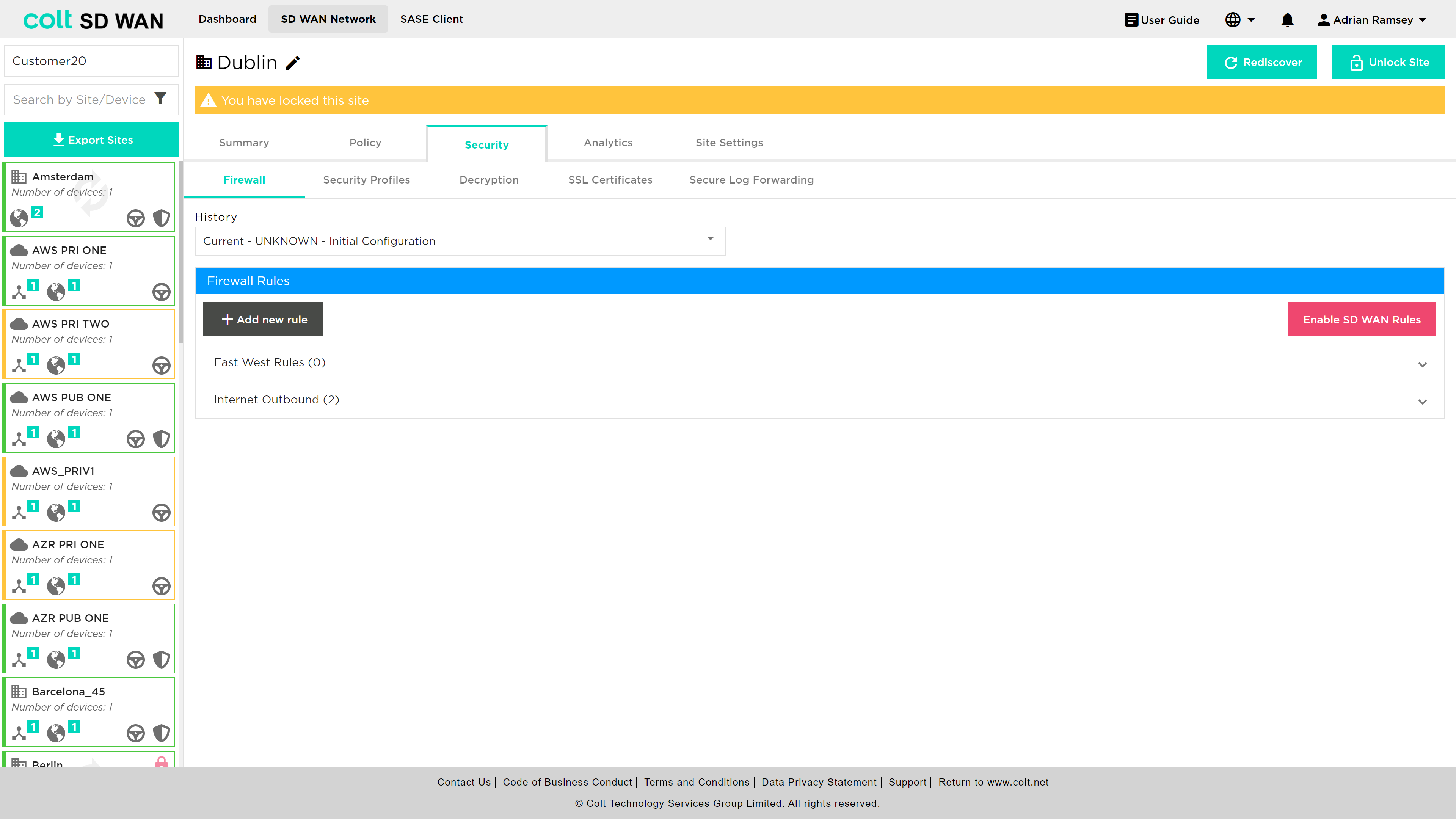
Firewall
The Firewall Management provides users with the ability to create, view, edit and capture log files for IP and application traffic between LAN, WAN and DMZ zones. In addition, traffic rules can be created for Local Internet Breakout (LIB) or over the SD WAN overlay network. These rules can apply to traffic inbound and outbound to the LAN and DMZ.
Management of Firewall rules via the SD WAN Portal is dependent on user role and if the site has a Firewall enabled.
Not all rules are visible. Bespoke rules can be provisioned directly into the Versa Director due to specific customer requirements outside the current SD WAN product description. Bespoke rules can be made visible, but editing those roles isn’t possible by using the rule naming convention ‘COLT-’.
Not all sites will have the LIB and SD WAN Firewall enabled and will depend on the configuration and service requirements at each site.
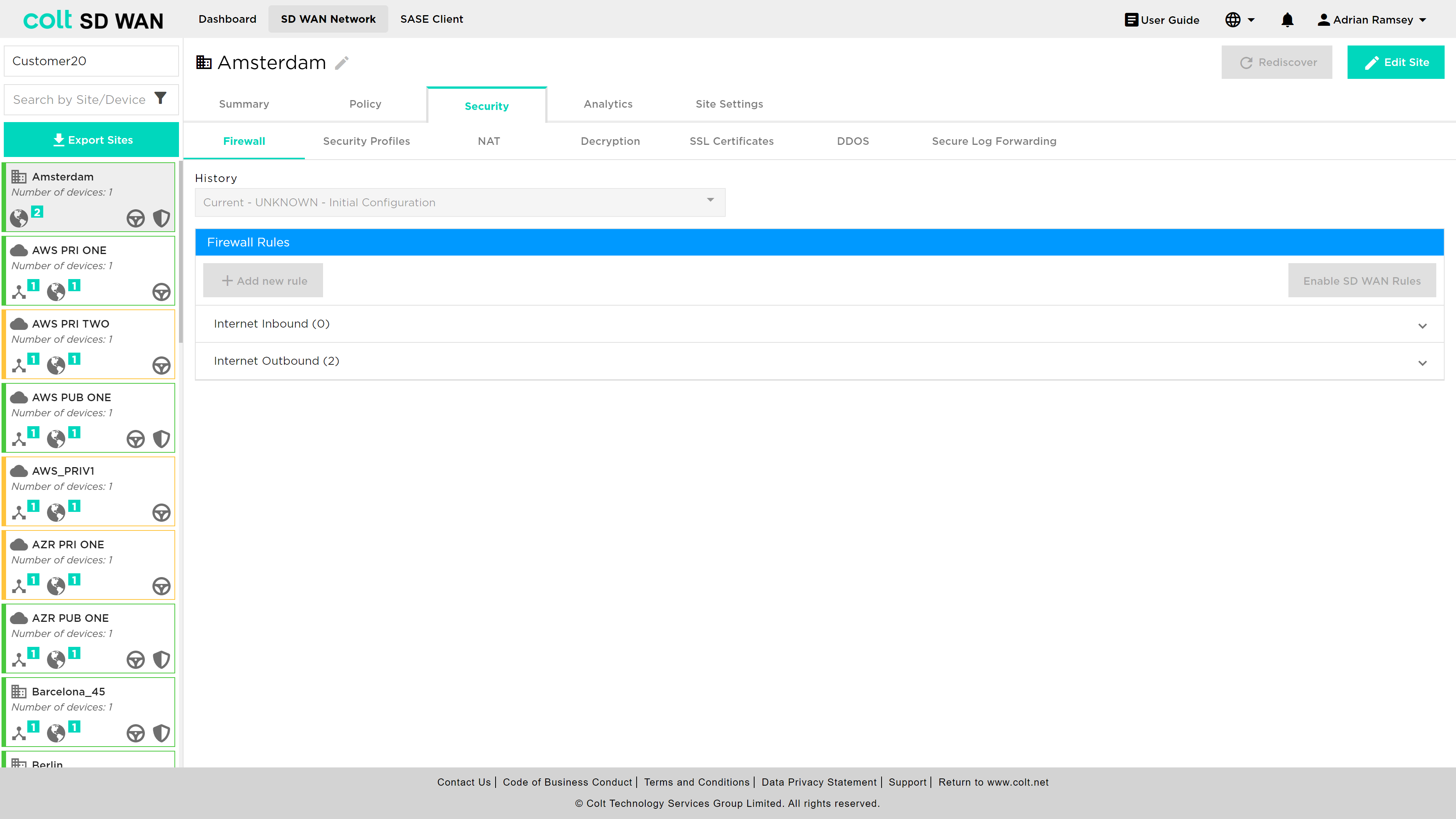
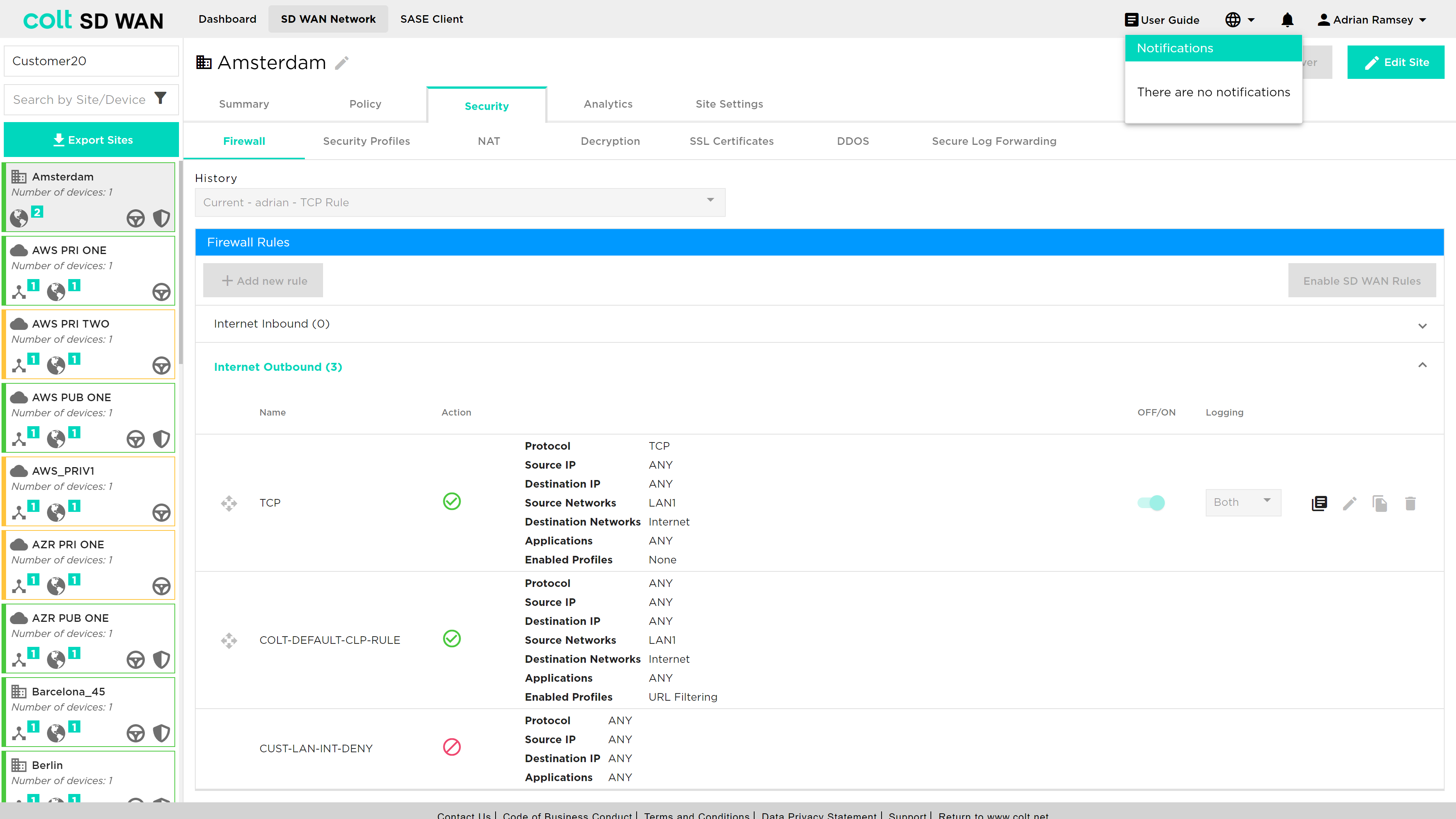
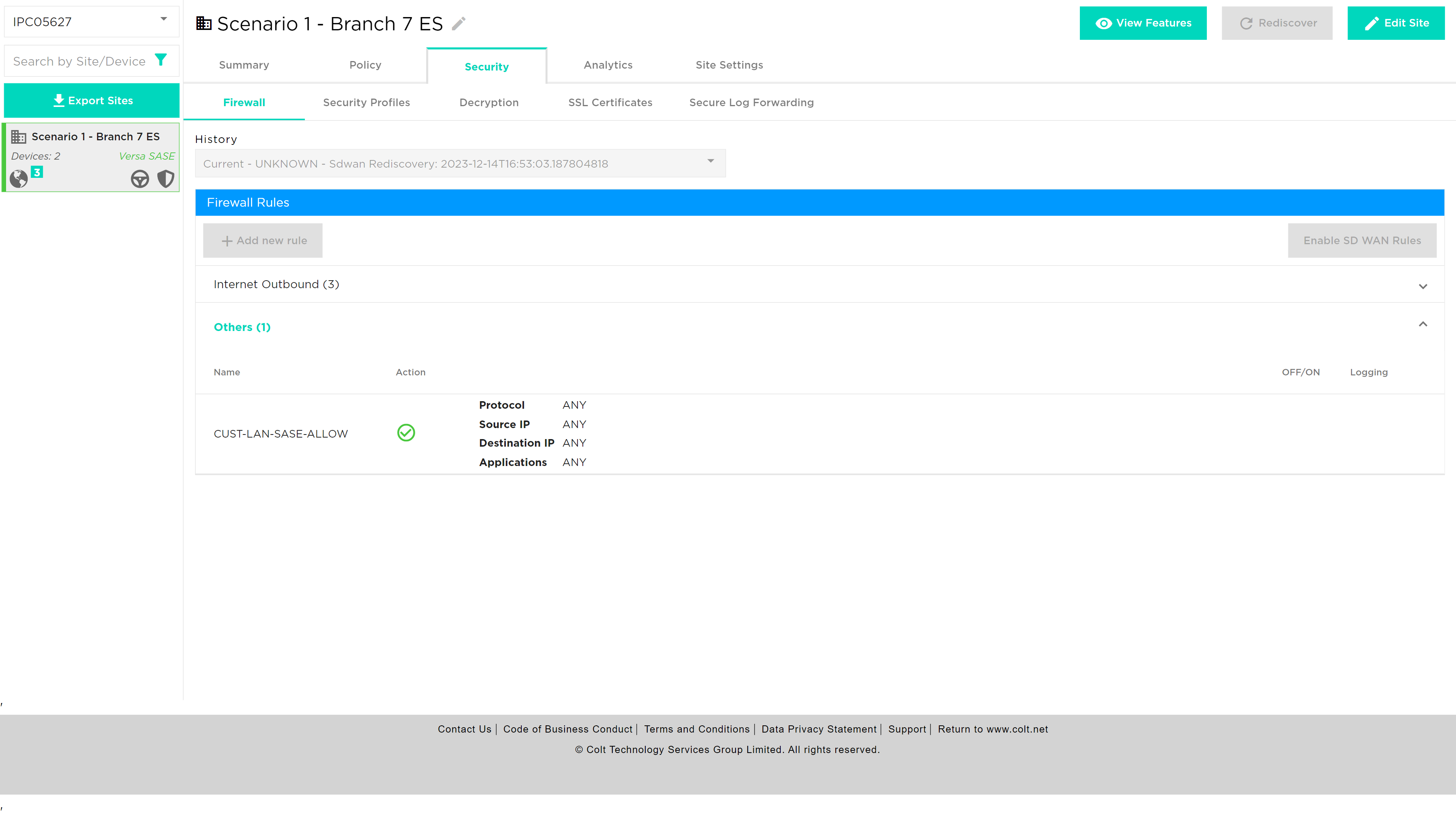
On delivery there is a single unchangeable rule that denies all traffic from the LAN to the Internet. Rules can be added above it to allow or deny access to the internet, based on application, protocol, addresses and port numbers.
Pre-created, or existing rules can be enabled, disabled or deleted. Likewise logging can be enabled or disabled by slide buttons associated with each rule. Log files can be viewed as text or downloaded in CSV format files.
Existing rules can also be edited by selecting them and using the edit button.
After this first step you can add source and destination ports, as well as the IP addresses which the rule applies to, and then specify the action you would like to take upon that, either allowing, denying or rejecting traffic. If no addresses or ports are added the rule will apply to all for that protocol. Where addresses are added they must specify a subnet, e.g. 10.1.1.0/24. For a single rule multiple address ranges/subnet can be added with the ‘ADD +’ button. Ports can be added as a single port, e.g. 45000, or a range, e.g. 45000-50000.
Rules are applied after the “Add” button is clicked. There is a short period of time (a few seconds) before the rule is submitted and it take effect at the site.
You can always add new rules to apply by clicking on the ‘Add New Firewall Rule’ button or delete them by clicking on the trash bin.
You can change the priority of rules by dragging them holding the mouse left button and dropping them where required in the list off rules.
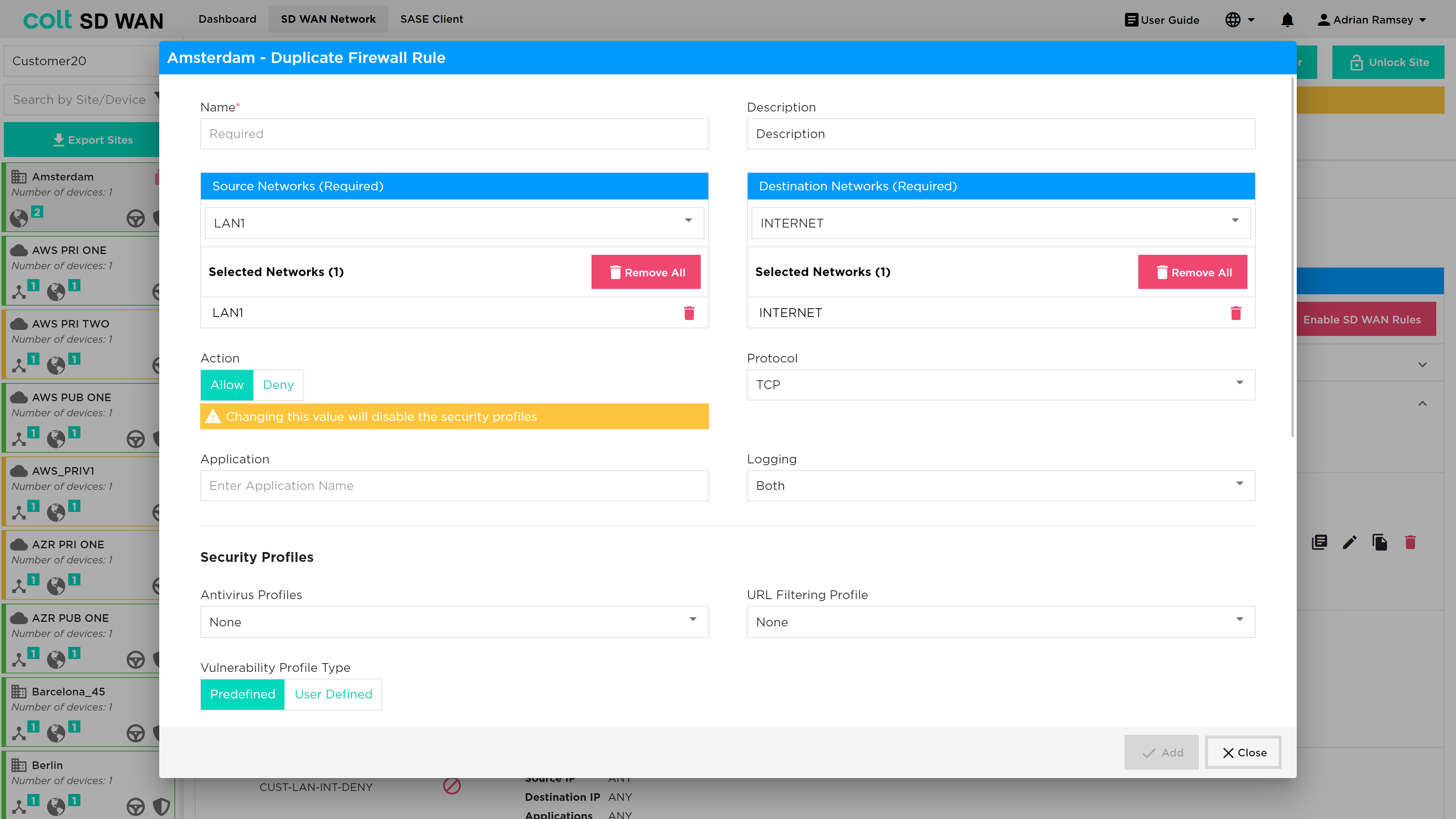
Rules can be duplicated using the duplicate icon as shown below.
You can revert to an older rule set by clicking the drop down in the top centre of page title ‘Current’ and select a version and click revert.
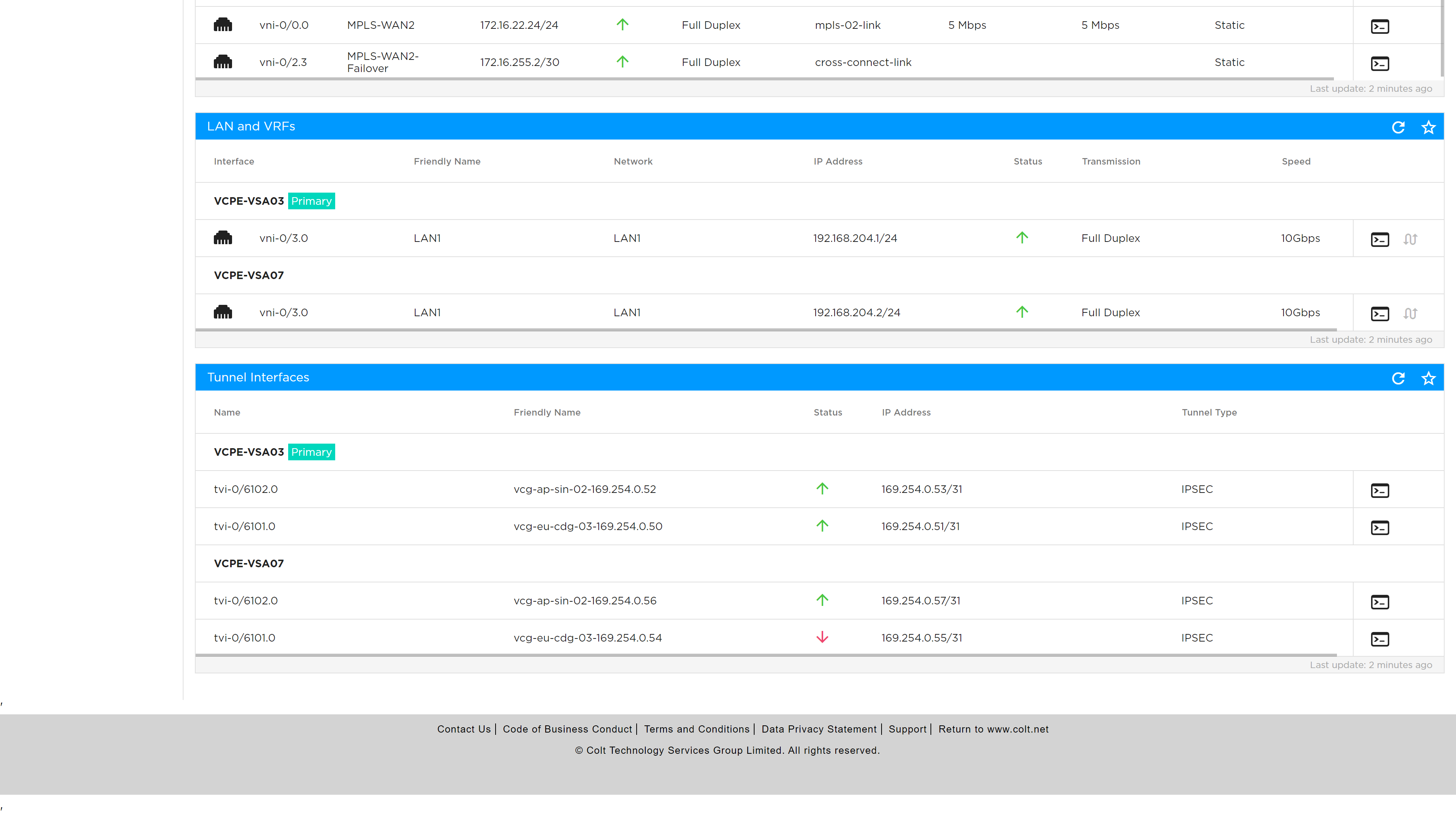
IPv6: There is the chance to verify IPv6 is present in Summary page under LAN and VRF’s section. User can enter an IPv6 address wherever IP address is allowed, except under Internet Traffic.
Click on ‘Add new Firewall (for SD WAN traffic only)’ / ‘Add new Policy’ to create a rule with IPv6 addresses.
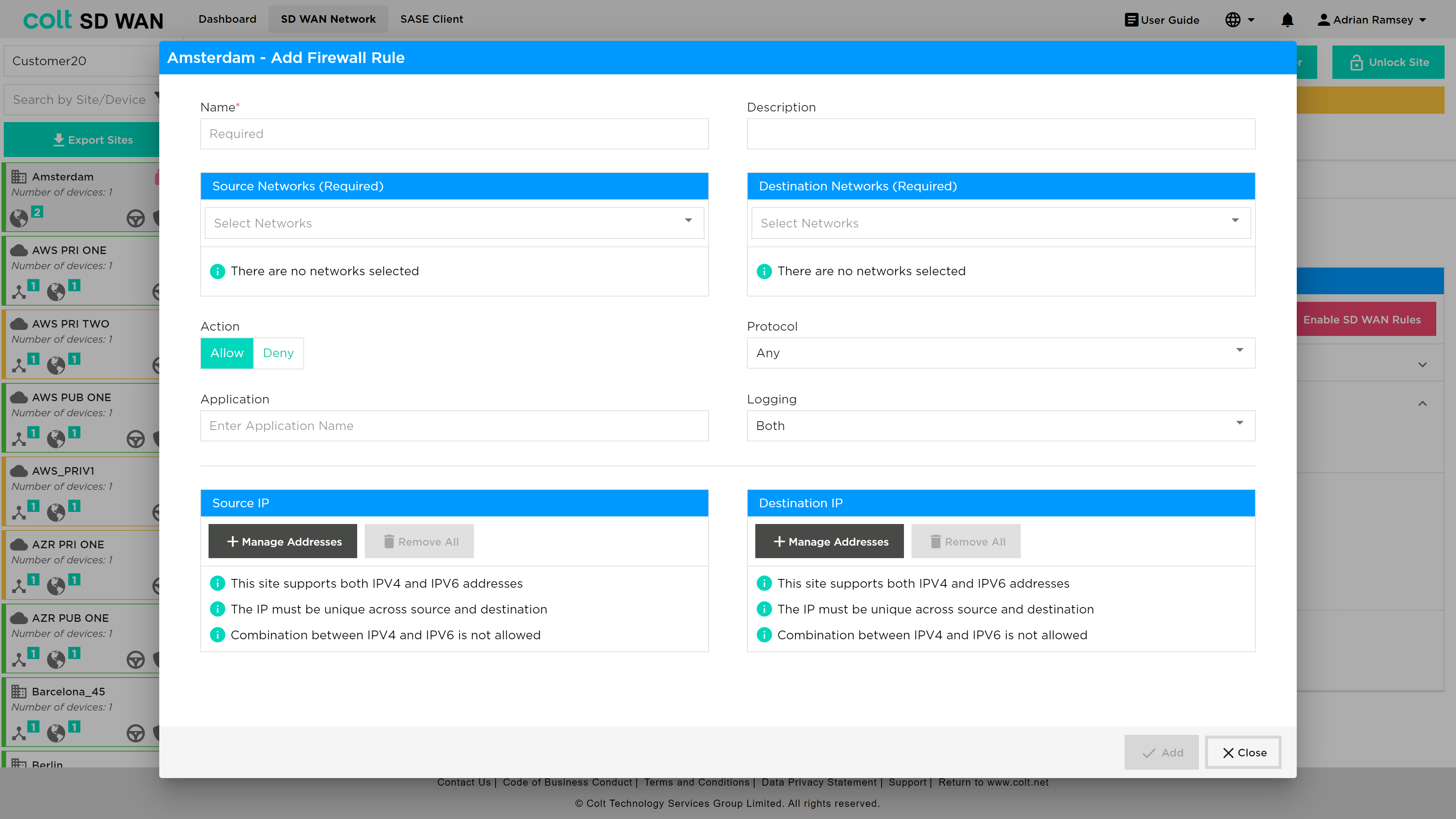
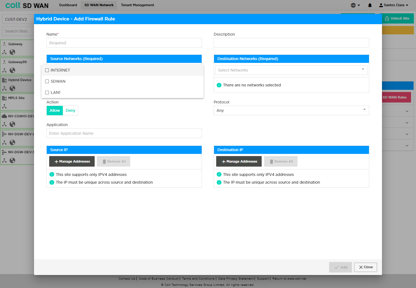
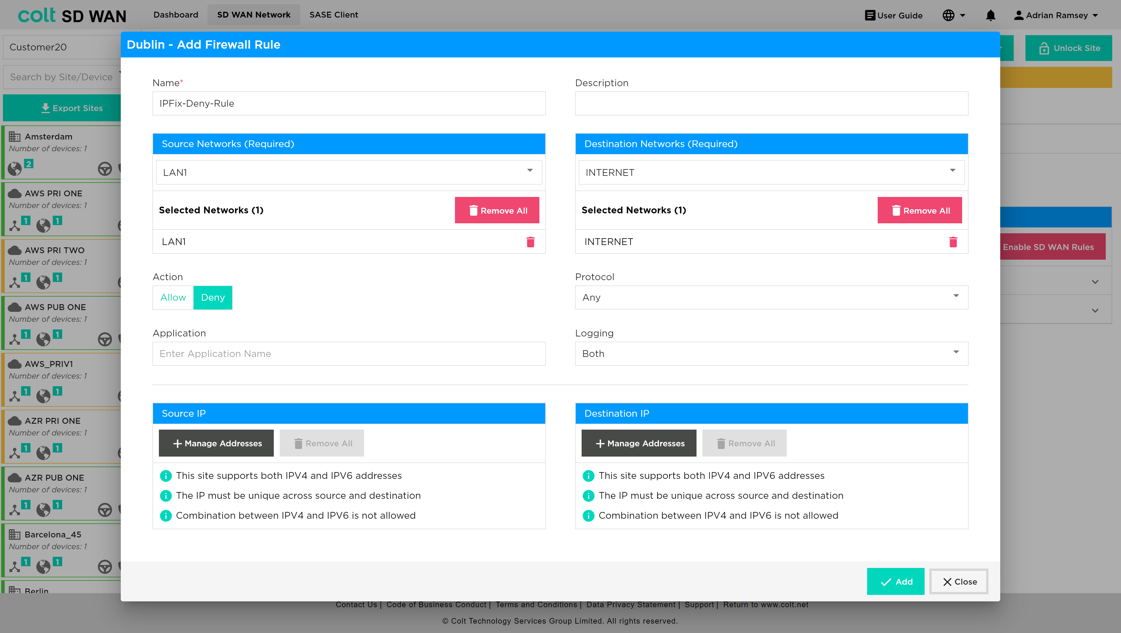
Firewall rules can be created using the ‘Add new Firewall rule’ button. New rules can be created for Internet Inbound and Outbound traffic or SD WAN Inbound and Outbound traffic. Mandatory options for new Firewall rules require the following fields to be completed:
-
Name – Representative name, no spaces
-
Source Networks
-
Destination Networks
-
Action – Allow, deny traffic with this rule
Specific match criteria for the rule can be added, otherwise the default behaviour will allow or deny any traffic from the selected VPN depending on the direction of the traffic. In general, the match traffic can be:
-
Source IP – IP address or range, multiple address or ranges can be added
-
Destination – IP address or range, multiple address or ranges can be added
-
Protocol – Protocol per IP address match
-
Application – Selected from the drop down list
Once created, submitted, and committed, the Firewall rule logging is disabled by default. Firewall log rules can be enabled using the slide button option. Firewall log files can be viewed by selecting the “View Logs” icon for each rule, which displays a tabular view that can be downloaded as a CSV file.
| log file space is limited to 10,000 per customer and therefore high usage of log file collection may result in records being overwritten or lost. |
Security Profiles
Anti-virus
| To enable Anti-virus profiles, they should first be created under the “Security Profiles” tab, and then subsequently associated to a specific firewall rule. Anti-virus is a chargeable feature under the name ‘Security+’ (together with IPS Vulnerability). The feature needs to be purchased before the functionality will be visible in the Portal. |
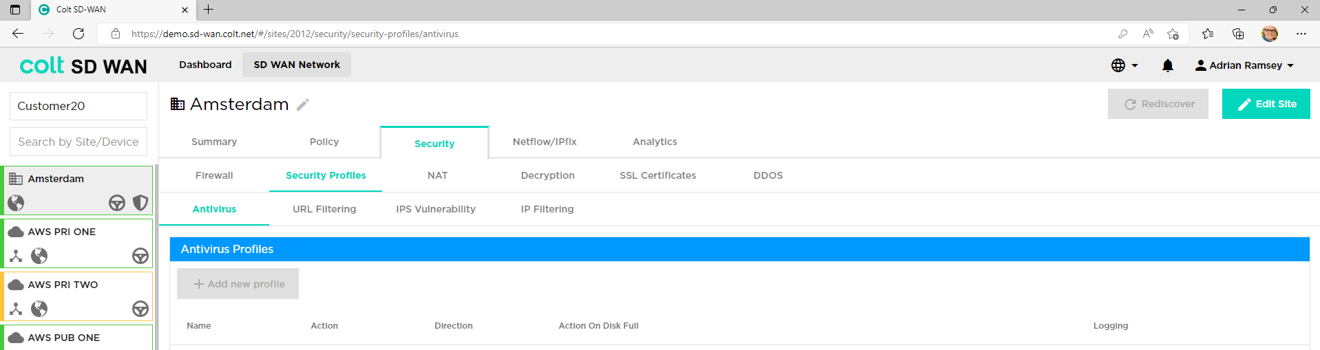
Versa SD WAN supports an Anti-virus capability. This is selected from the ‘Security’ tab and under this the ‘Security Profiles’ tab. After the entire file is received, extracted and buffered, the file is transferred to the destination except the last data packet. Once the virus scan is performed the rest of the file is transferred or blocked to the destination depending upon the action defined in the policy.
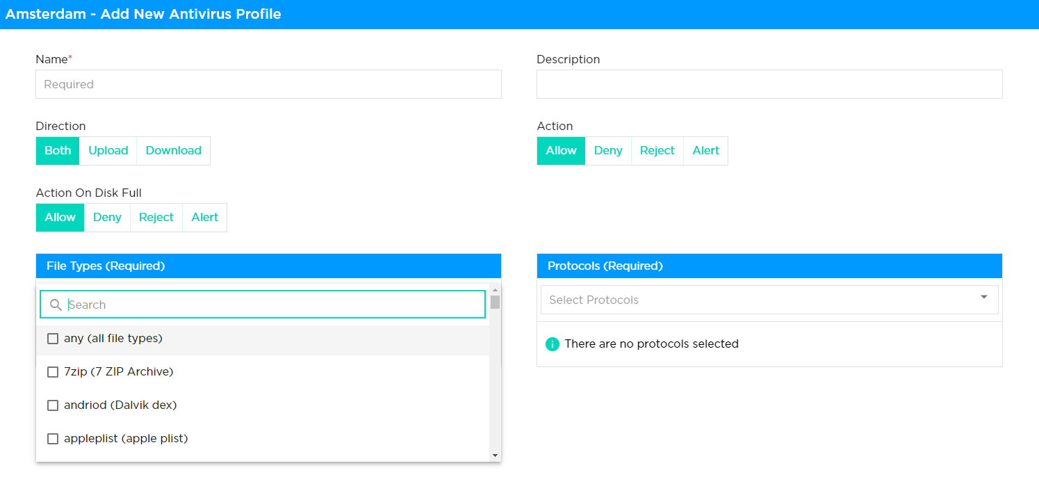
Following are the requirements to be referred for development of Antivirus solution
-
Name: Name of the rule being defined
-
Description: Description of the rule being defined
-
Direction: The user needs to select the antivirus scanning of file extracting only from Upload or Download direction, or both.
-
Action: The user needs to define the action taken on the file type in question, either Allow, Deny, Reject or Alert. This also needs to be defined for when the disk is full.
-
Action on disk full: As above but in the situation that the disk is full.
-
File Types: The user selects the file type that the extraction should apply to, for example ppptx, torrent, appleplist, doc, jpeg, msi and many others.
-
Protocols: The user selects the protocols that the extraction should apply to, for example FTP, HTTP, IMAP, POP3, SMTP.
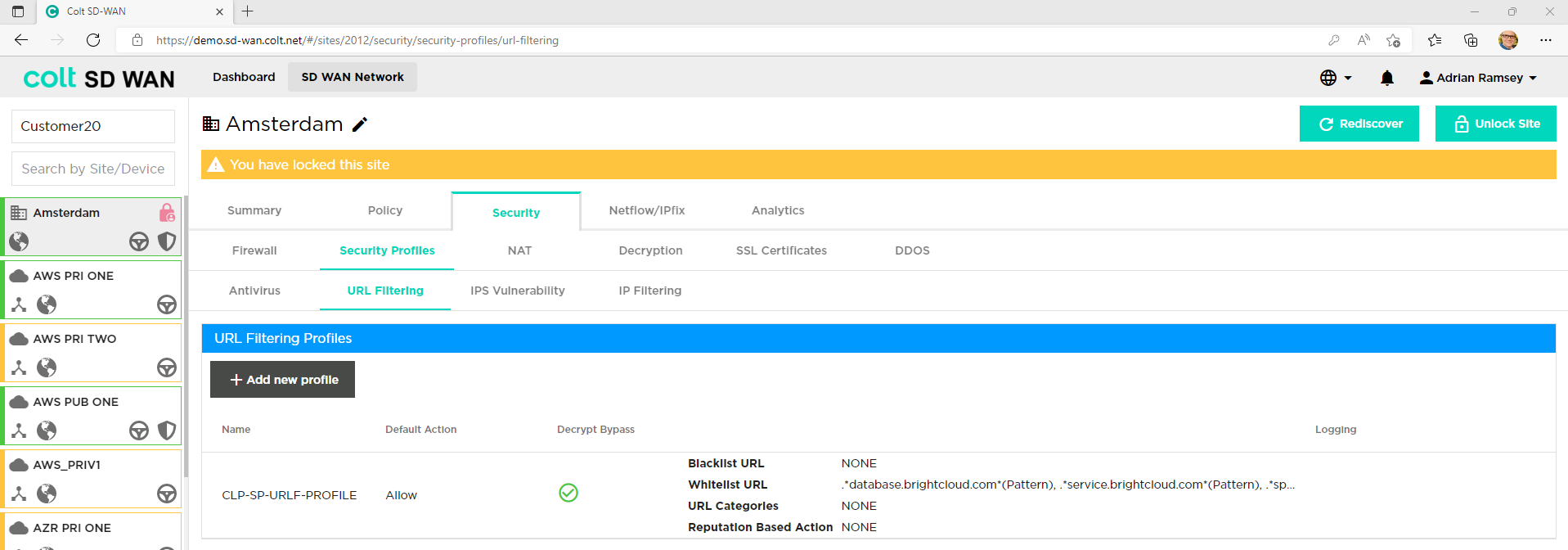
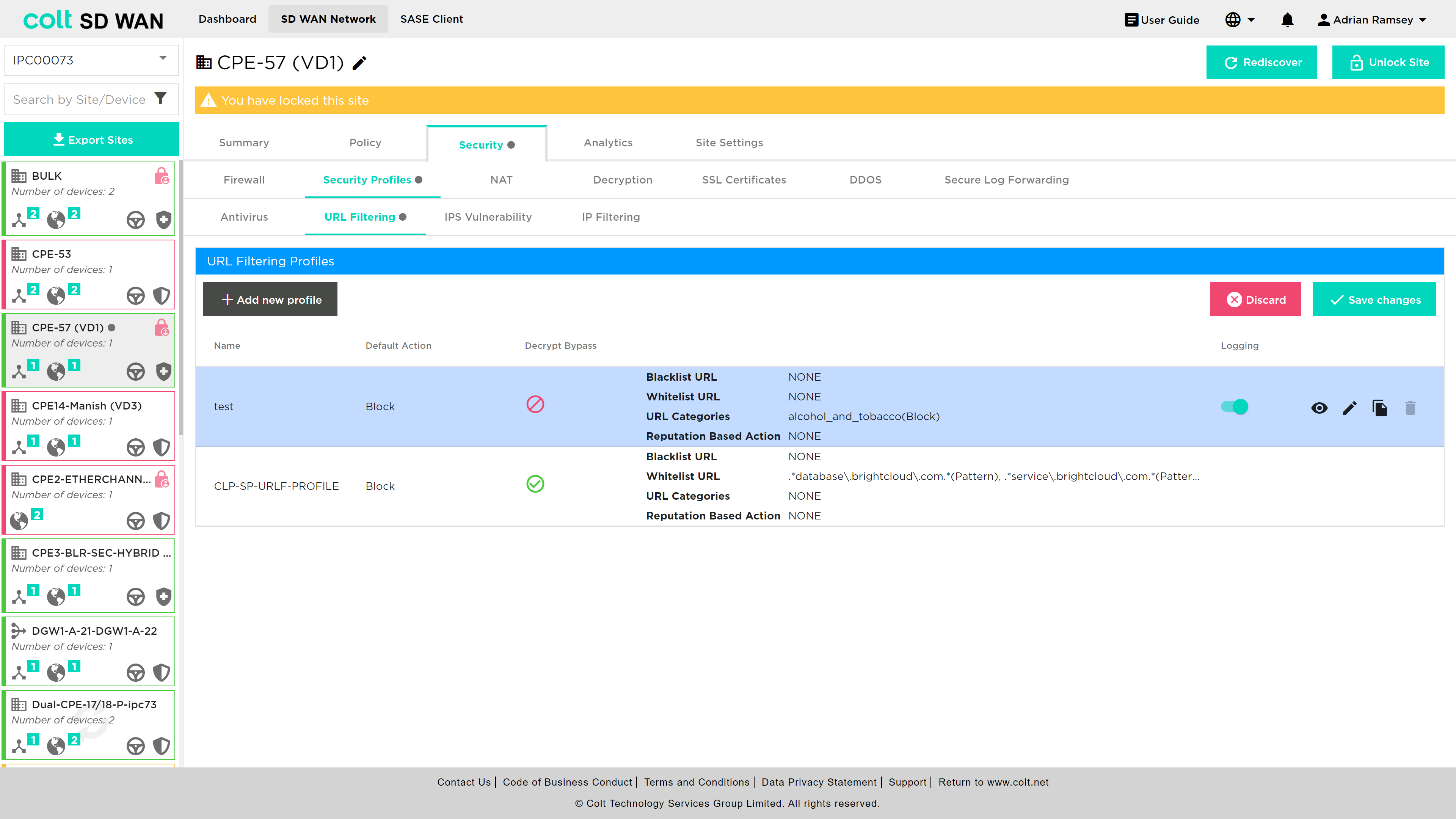
URL Filtering
| To enable URL Filtering profiles, they should first be created under the “Security Profiles” tab, and then subsequently associated to a specific firewall rule. |
The SD WAN Portal allows users to create and manage rules that override the default behaviour for each category of URL. These rules are created by defining URL filtering profiles which are then associated with firewall rules.
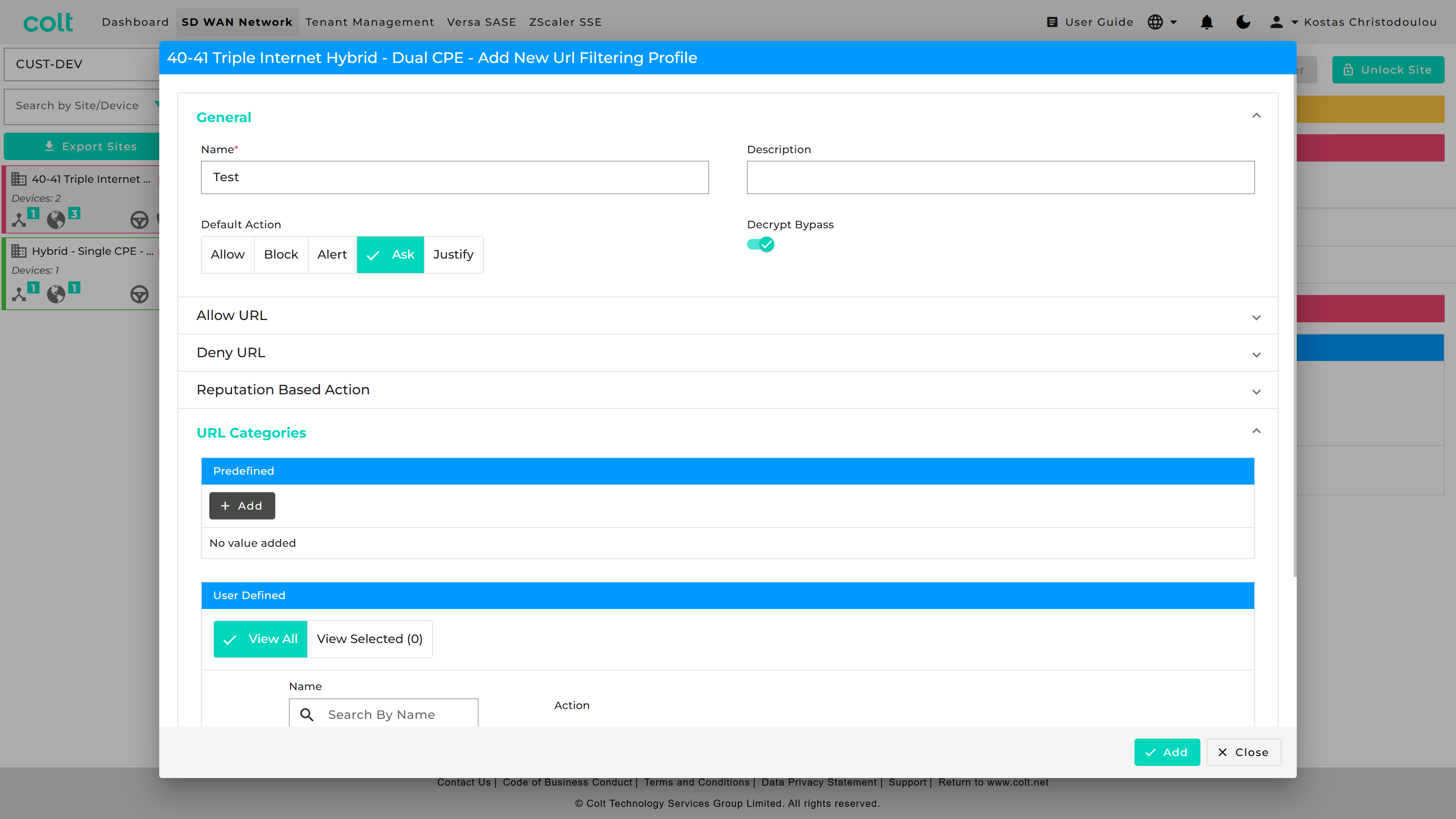
In order to start the process of adding or editing URL filters user has to: Edit the site, select Add or edit firewall rule, select outbound rules and select action apply security profile to configure URL filtering:
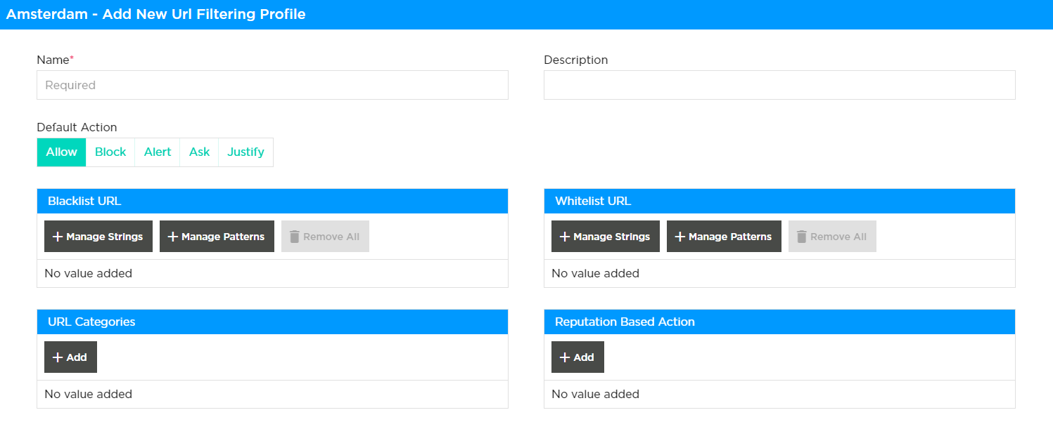
A default action can be enabled for all URL, categories or threats with exceptions being added as individual Whitelist, Blacklist, Category or Reputation rules. The actions available are as follows:
-
Alert: Allow the URL and generate an entry in the URL filtering log.
-
Allow: Allow the URL without generating an entry in the URL filtering log.
-
Ask: The browser presents an information page that allows the user to either cancel the operation by clicking Cancel or continue with the operation by clicking OK (for HTTP and HTTPS).
-
Block: Block the URL and generate an entry in the URL filtering log. No response page is displayed, and the user cannot continue with the website.
-
Justify: The browser presents an information page that allows the user to either cancel the operation by clicking Cancel or continue with the operation after entering a justification message and clicking OK (for HTTP and HTTPS).
| For HTTPS (encrypted) websites, a block or captive portal page is only displayed when SSL decryption is enabled. If SSL decryption is not enabled, blocked HTTPS connections are reset or dropped. |
| Actions specific to category and reputation will take precedence over the default action. If any of the URLs are categorized or have certain reputation selected for filtering, then the highest severity action will be used for traffic filtering. The customer can choose to apply either a single filtering methodology or to utilize multiple filtering options like category, reputation, blacklist, whitelist. |
| Regex expressions are provided by the user. There are several reference guides providing lists and usage of regex. An example of which, can be found here. |
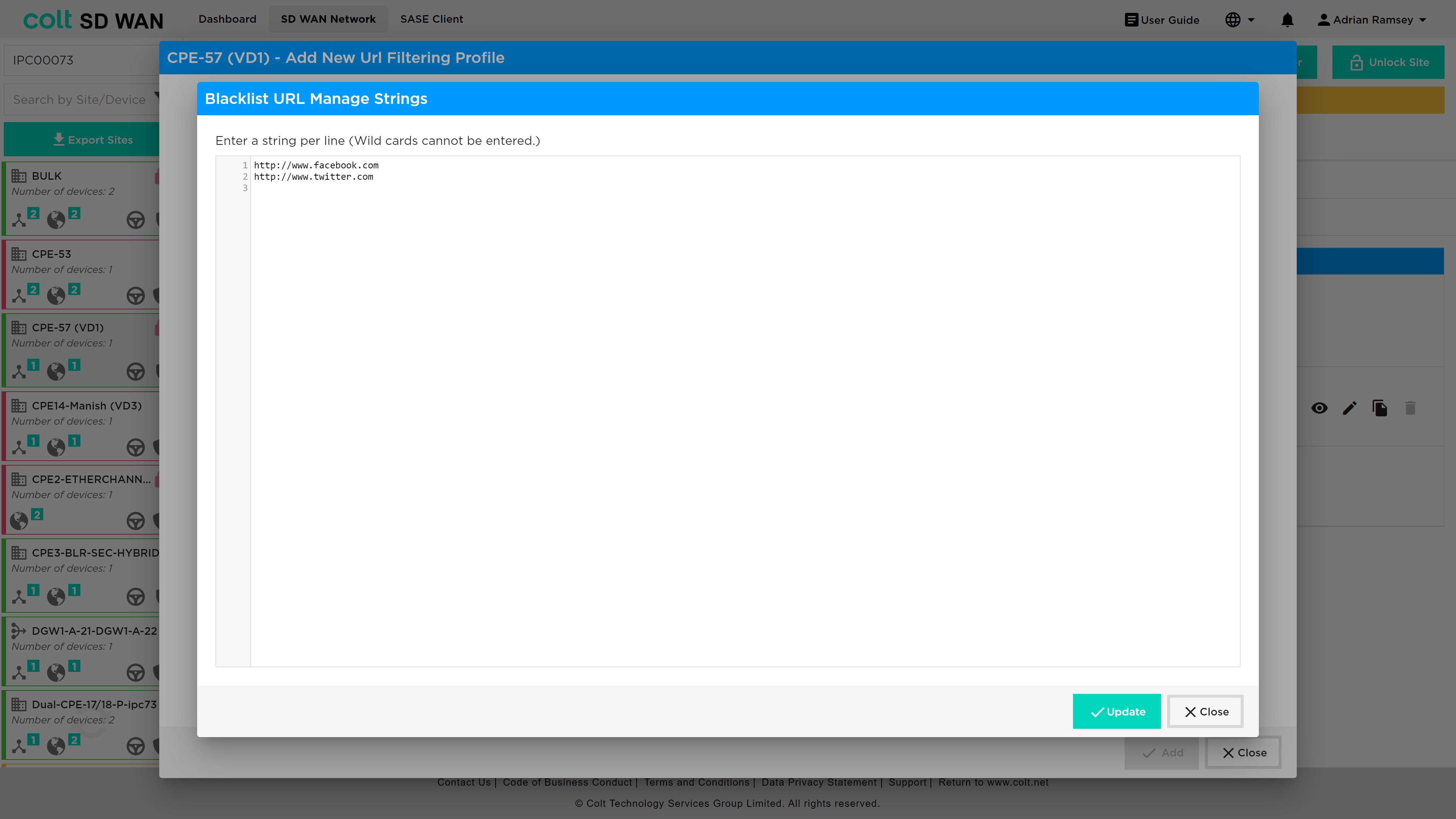
Black and White list rules can be created for single URL or expressions as shown below, with options that override the default – Alert, Allow, Block. Multiple strings or patterns can be added for the same rules. The definition of Black and Whitelist behaviours are as follows:
Blacklisted URLs:
-
You can specify either fixed strings or regex patterns to match the blacklist URL. Specify the blacklist action that you want to enforce for all the matching HTTP flows. If the blacklist action is not configured, the default drop session action is enforced.
Whitelisted URLs:
-
For whitelist URLs, you can specify either fix strings or PCRE patterns to match the whitelist URLs. The URLs that match the whitelist configuration are allowed without enforcing any security actions. Optionally, you can enable logging in the whitelist configuration to receive whitelisted URLs access.
The following table defines the behaviour of the URL Filtering and Captive Portal policy, action and the end user devices.
| CP -Working Conditions | URLF-Policy CP action-Ask/Justify | SSL Decryption policy | Certificate installed in End user system |
|---|---|---|---|
Captive portal works |
Yes |
Yes |
Yes |
Captive portal Not work |
No |
No |
No |
No |
Yes |
Yes |
|
No |
No |
Yes |
|
Yes |
No |
No |
|
Yes |
Yes |
No |
| Patterns and strings can be entered in list form or pasted into the list view so that multiple URL and patterns can be configured in a single URL Filter. |
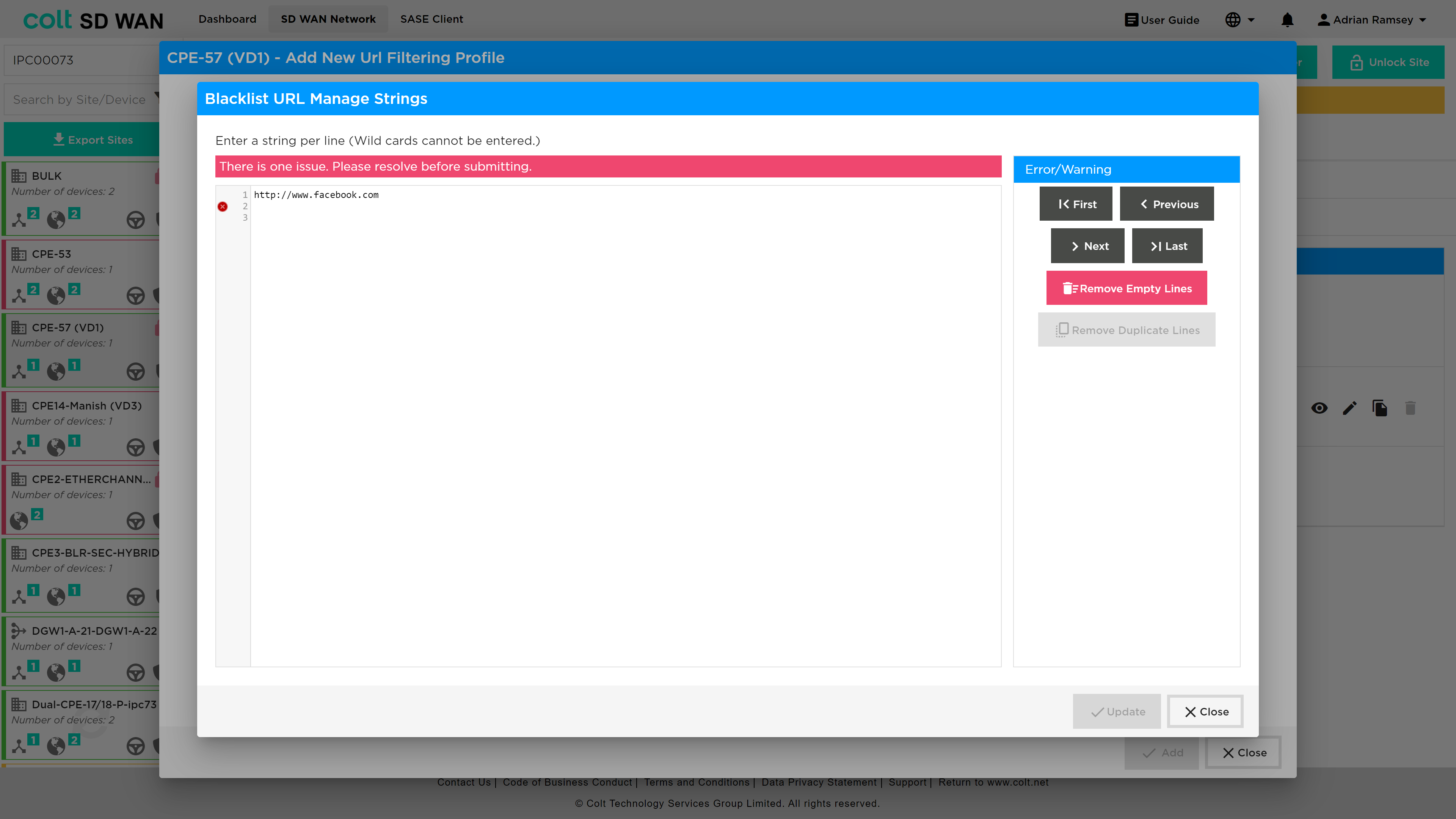
With pattern matches, the regular expression is validated and warning is shown if expressions are invalid.
Likewise, URL category and reputation can be set as shown in the screen shot below.
The order of precedence is based on the following priority value, with the highest value taking precedence:
{ 1, VP_POLICY_ACTION_ALLOW },
{ 2, VP_POLICY_ACTION_INFORM },
{ 3, VP_POLICY_ACTION_ASK },
{ 4, VP_POLICY_ACTION_JUSTIFY },
{ 5, VP_POLICY_ACTION_OVERRIDE },
{ 6, VP_POLICY_ACTION_BLOCK },
{ 7, VP_POLICY_ACTION_RST_CLNT_SRVR },
{ 8, VP_POLICY_ACTION_DROP_PKT },
{ 8, VP_POLICY_ACTION_DROP_SESS },
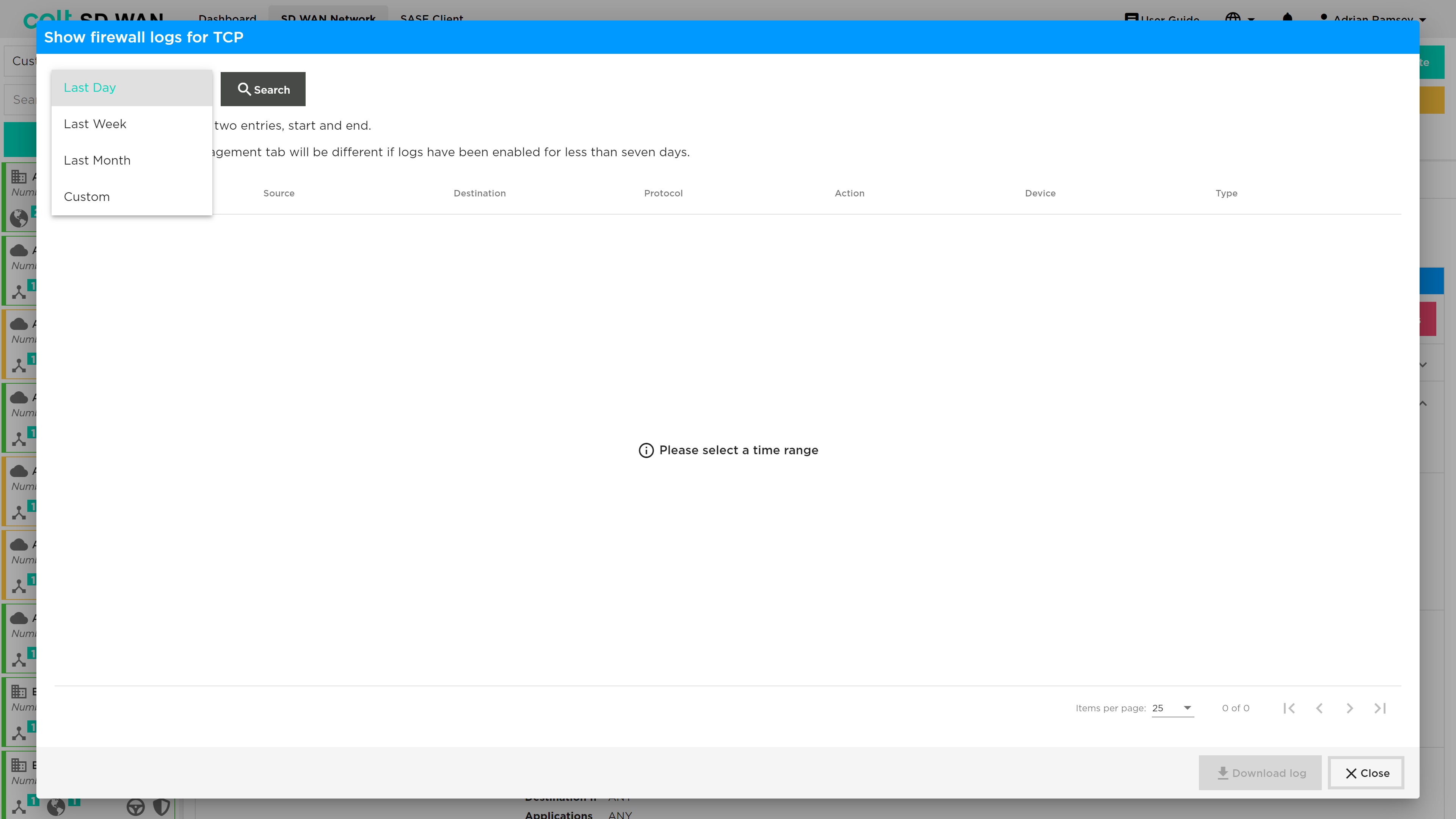
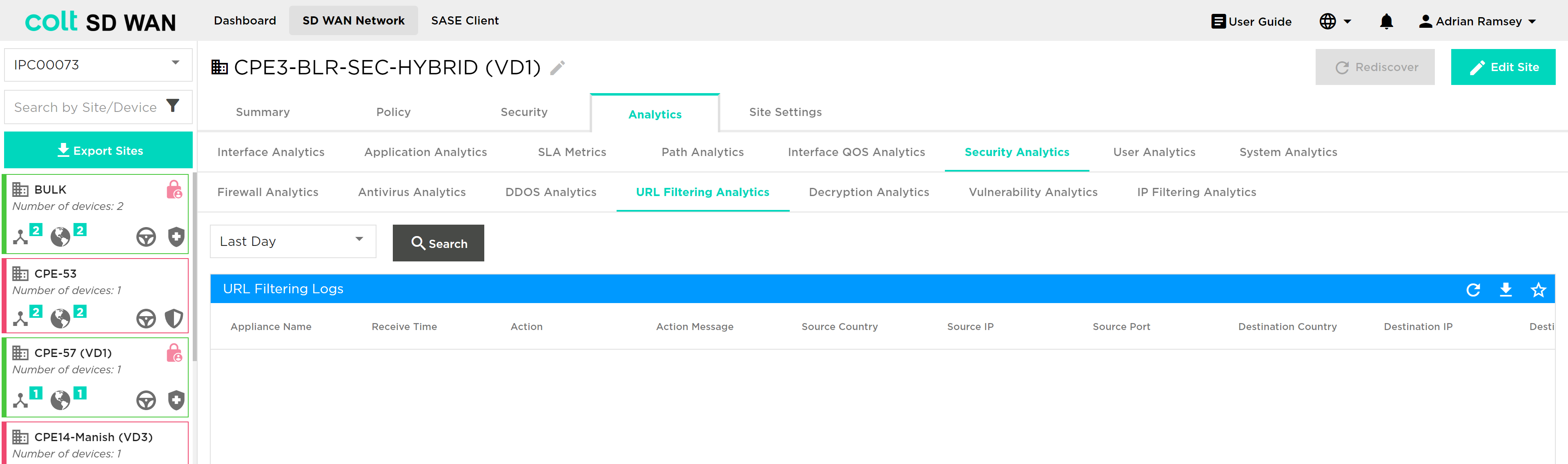
URL Filter logging of Allow URLs can be enabled or disabled per rule in the same way as Firewall or DDOS rules are. To View URL Filter log files´ rules, select and search for the period of log file history from Day, Week, Month or Custom Date.
The URL log file is presented in a text based tabular view as shown below. They can be downloaded as CSV files.
Decryption Bypass in URL Filtering:
You can create Custom URL Categories that will appear in the URL Categories tab for URL filtering with possible actions of Allow and Alert.
Use URL Categories in URL Filtering profiles: Security > Security Profiles > URL Filtering
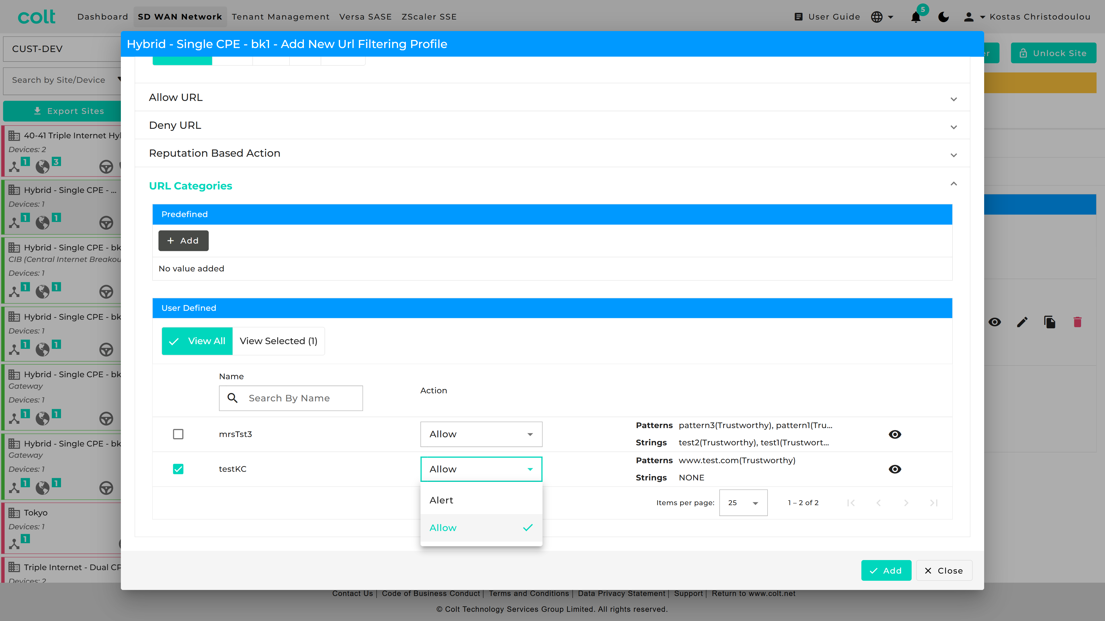
You can make use of decryption bypass in a URL Filtering profile, by referencing a User Defined URL category that has been created in the Objects tab.
IDS/IPS Vulnerability
| To enable IPS Vulnerability profiles, they should first be created under the “Security Profiles” tab, and then subsequently associated to a specific firewall rule. IPS Vulnerability is a chargeable feature under the name ‘Security+’ (together with Anti-virus). The feature needs to be purchased before the functionality will be visible in the Portal. |
Versa FlexVNF provides the IDP feature to defend against the malicious exploitation of vulnerabilities within various underlying software/hardware within the customer´s network. It will be supported from Next Generation Firewall service enabled CPEs. Currently the following functionality is supported:
-
User-Defined vulnerability profile: User-Defined vulnerability profiles have many attributes and options which can be customized as per the user’s requirements. It uses a user-defined signature database for vulnerability protection. The signature database is constantly updated via the Security package. Colt update the Security package frequently.
-
Predefined vulnerability profile: Predefined vulnerability profiles are predefined and cannot be modified. Predefined vulnerability profiles use their own set of signatures for vulnerability protection. The predefined profile can be directly attached to the Security access policy. The signature database keeps updated via the Security package. Colt update the Security package frequently.
Currently supported predefined vulnerabilities by Versa:-
All Anomaly Rules—This profile loads all the anomaly signatures.
-
All Attack Rules— This profile loads all attack signatures.
-
Client Protection— This profile loads all client-side attack detections.
-
Database Profile—This profile loads the oracle database server vulnerability signatures.
-
ICS Profile—This profile loads the Industrial Control System (ICS) vulnerability signatures.
-
Linux OS Profile—This profile detects all attacks specific to Linux OS.
-
MAC OS Profile—This profile detects all attacks specific to MAC OS.
-
Malware Profile—This profile detects all antivirus attacks.
-
Server Protection—This profile detects server-side attack detections.
-
Windows OS Profile—This profile detects attacks specific to all windows OS.
-
Versa Recommended Profile
-
-
Override the Vulnerability profile: Override profile is used to modify the action defined in the predefined vulnerability profile. If the action type in predefined profile is rejected, it can be changed to alert using the override profile.
-
Predefined Signature: Versa provides the predefined signature via security package updates. Colt shall update the package accordingly
-
Unified Threat Monitoring / Analytics: The SD WAN Portal shall display the top threats and vulnerabilities with signature IDs from different sources/destinations.
To create an IDS profile the user should select Security – Security Profiles – IPS Vulnerability as shown below from which the addition of User Defined or Predefined Override Profiles can be selected:
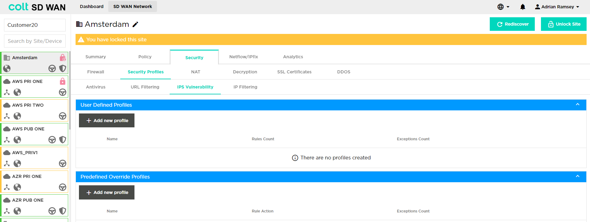
If the user would like to add a new User Defined Profile, they need to click on "+ Add new profile", then "+ Add new rule" and the following window opens:
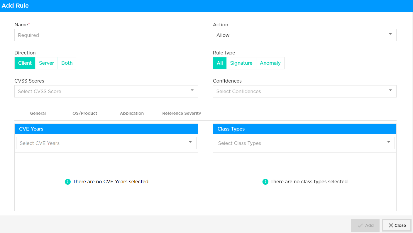
The user then needs to insert the following details:
-
Name: Name of the rule being defined
-
Action: Action on match – either Allow, Alert, Drop Packet, Drop Session, Reject
-
Direction: Client, Server or both
-
Client Protection: Client requests which gets initiated to a host server, hosting web, mail, file service etc. are protected to prevent the user from downloading a virus and/or preventing intrusions.
-
Server Protection: For those customers who wish to publish their services to the internet, protection can be applied for such incoming malicious attempts. In such case the protection can be applied in the firewall rule where access is enabled for the server. In this example all incoming traffic to the services are inspected through IDP & AV and the clean traffic gets forwarded to the server.
-
-
CVSS Scores: The Common Vulnerability Scoring System (CVSS) provides a way to capture the principal characteristics of a vulnerability and produce a numerical score reflecting its severity. The numerical score can then be translated into a qualitative representation (such as low, medium, high, and critical) to help organizations properly assess and prioritize their vulnerability management processes.
-
Confidences: This metric measures the degree of confidence in the existence of the vulnerability and the credibility of the known technical details. Sometimes only the existence of vulnerabilities is publicised, but without specific details. For example, an impact may be recognized as undesirable, but the root cause may not be known. The vulnerability may later be corroborated by research which suggests where the vulnerability may lie, though the research may not be certain. Finally, a vulnerability may be confirmed through acknowledgment by the author or vendor of the affected technology. The urgency of a vulnerability is higher when a vulnerability is known to exist with certainty. This metric also suggests the level of technical knowledge available to would-be attackers.
-
General: CVE Years, Class Types - CVE stands for Common Vulnerabilities and Exposures. A unique, alphanumeric identifier assigned by the CVE Program. Each identifier references a specific vulnerability. A CVE ID enables automation and multiple parties to discuss, share, and correlate information about a specific vulnerability, knowing they are referring to the same thing. Class types generally refer to the type of vulnerability.
-
OS/Product: CVE Years, Class Types – as above.
-
Application: Details about specific applications
-
Reference Severity: Any details about the reference severity.
Additionally, the user can define exception rules (Select "+ Add new rule" and then click on the "Exceptions" tab) which will open the window below.
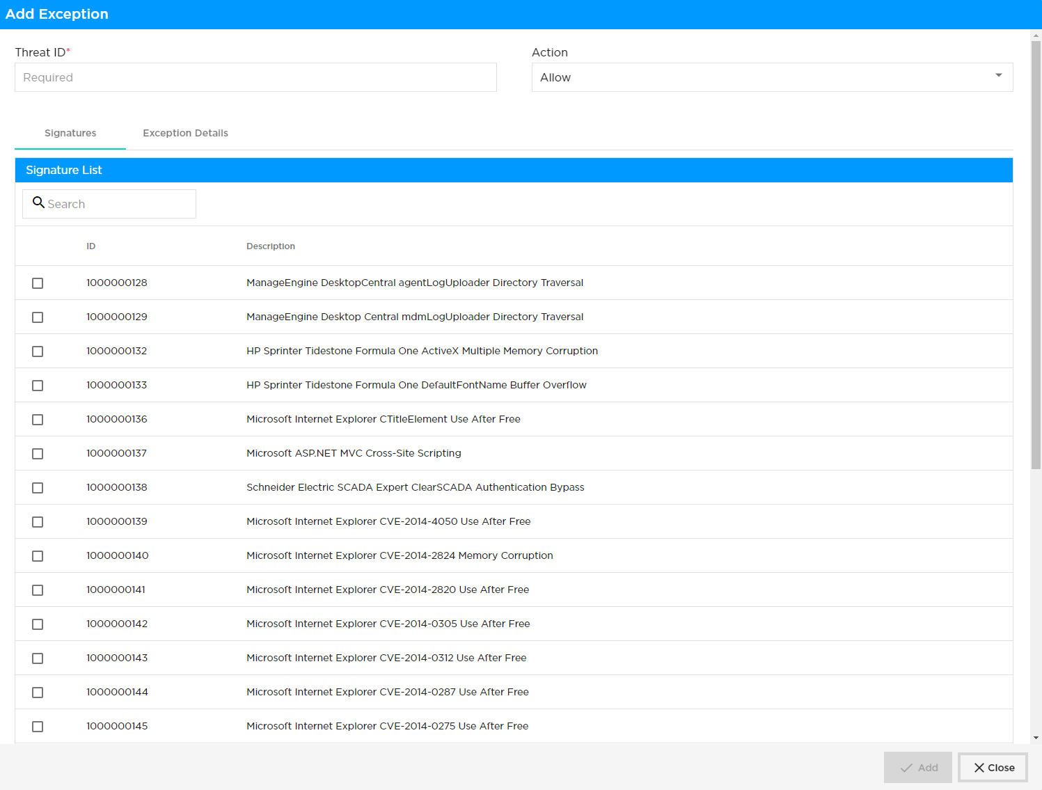
After selecting ‘Exception Details’ tab, specified IP addresses can be added under the exception list and they will be bypassed.
IP Filtering
| To enable IP Filtering profiles, they should first be created under the “Security Profiles” tab, and then subsequently associated to a specific firewall rule. |
Traffic passing through the network may have IP addresses that are associated with a bad reputation and that may pose a security risk to your network. It is part of Colt’s IPS feature to block these IP addresses. This can be done based on IP address reputation and IP address metadata such as geolocation. You can configure IP address filtering profiles and then associate them with a security policy.
IP filtering is based on the reputation associated with an IP address and its geolocation where you can filter traffic based on IP reputation and IP address metadata (that is, geolocation). Versa Networks provides an IP reputation feed that is updated through SPACK updates. This will be supported from Next Generation Firewall (NGFW)service enabled CPEs.
Next Generation Firewall policy with IP filtering profile:
We should be able to configure one or more IP-filtering profiles under the NGFW access policy rules. This is enforced only for the traffic that matches that rule. IP filtering Profiles support user defined profiles where you are allowed to create rules for both IP reputation and Geolocation based filtering. Each IP filtering profile consists of the following:
-
Rules for geolocation-based actions- It will be supported with either one or multiple actions in one profile
-
Rules for IP reputation–based actions -It will be supported with either one or multiple actions in one profile
IP reputation:
IP filter profile supports using the following predefined IP reputations:
-
BotNets
-
Denial of service
-
Phishing
-
Proxy
-
Reputation
-
Scanners
-
Spam sources
-
Web attacks
-
Windows exploits
Geolocation:
Colt provides a list of predefined regions that offered by Versa, that you can use to create IP filter profiles based on geolocation. In addition, this will support matching the IP address based on the following match criteria:
-
Source IP address
-
Destination IP address
-
Source or destination IP address
-
Source and destination IP address
You can enforce the following actions when a session’s IP address matches the conditions in the IP filtering profile:
-
Allow
-
Alert
-
Drop packet
-
Drop session
-
Reset
| The default action will be in effect, if the user-defined actions are not matched for the customer traffic, similar to URLF. The IP filtering profile will override the URL filtering profiles (URLF), even if they match the same traffic pattern. Therefore, it must be created accordingly to meet customer requirements through the SDWAN portal. |
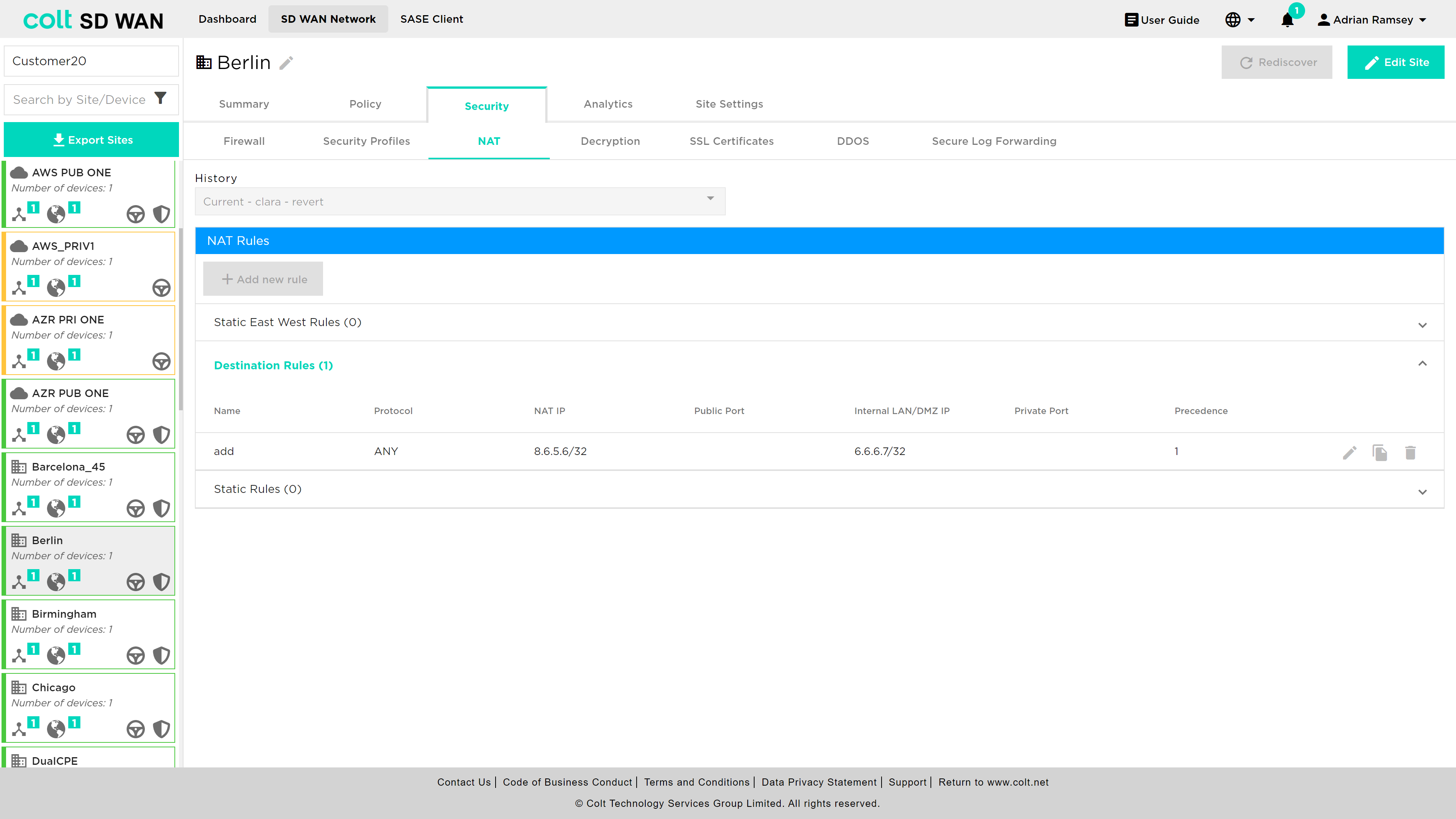
NAT Rules
Static/DNAT is available for Advanced Firewall services and for Internet inbound and outbound traffic. The NAT rules are viewed and configured through a separate menu of options as shown below. The NAT rules are for DNAT and Static NAT. Each option provides the ability to view, edit and add.
DNAT rules
DNAT rules apply to traffic inbound from the Internet WAN link and is supported as standard on single CPE. A single CPE with multiple Internet links only supports DNAT on the primary Internet link.
| DNAT/SNAT is not supported for Dual CPE in the SD WAN portal but is available as a bespoke solution. |
Rules can be viewed and edited as other Firewall rules by selecting the rule and then selecting "Edit" to make changes. New rules can be added using the "+ Add new rule" button. When the DNAT rule is created, the access control rule has to be created manually with allow action for the set of IP addresses, port and protocol. Please see screenshot below.
|
The following fields are configured for DNAT:
-
Name: Rule name to reference or describe the rule
-
VPN: Private subnet the NAT target address will come from
-
Source IP: Source IP address and subnet from the Internet to the LAN
-
Public IP: WAN IP address that should be matched to translate the IP address
-
Protocol: Protocol type (drop down list) and port number to be matched by the inbound Internet traffic. The port number can be single or a range
-
Private LAN/DMZ IP: Target IP address and subnet for DNAT to translate public to private
-
Private LAN/DMZ Port: Target Port or Port range for DNAT to translate public to private
-
Action: Allow or deny the traffic
-
Direction: The DNAT can be applied for to traffic flowing both inbound and outbound to the LAN VPN
The screen shots below show the fields.
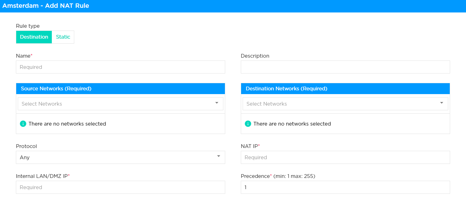
Static NAT
Static NAT rules apply to traffic inbound from the Internet WAN link and is supported as standard on single CPE or dual CPE with single Internet WAN link.
| SNAT is not support for Dual CPE in the SD WAN portal but is available as a bespoke solution. |
The Static NAT provides the ability to translate an IPv4 address assigned as either part of the WAN subnet or an additional IPv4 WAN subnet address pool to a single IP address on either the LAN or DMZ zones.
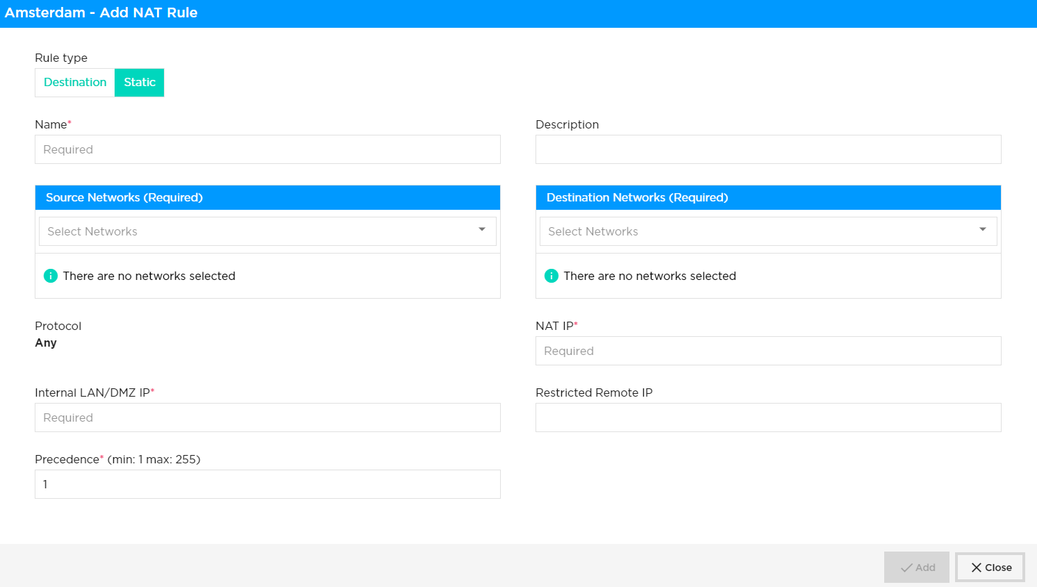
|
New rules can be added by selecting add new rule, the key fields are:
-
Name: Reference or description of rule (no blanks or spaces)
-
VPN: LAN/DMZ subnet that the NAT IP address will come from
-
Precedence: Order and priority to assign to this NAT, i.e. the same IP address can be used but with a different translation
-
NAT IP: Public IP address as a single IP with /32 as the mask
-
Internal LAN/DMZ IP: Single IP address from the AN or DMZ private subnet assigned to the VPN
| Restricted Remote IP – This is an optional field that helps to limit access by IP address (/32) when enabled with static NAT. This restriction will be applicable for bi-directional communication between client and server. |
Decryption
The decryption option allows rules for when decryption is and isn’t applied. This is only possible once a certificate has been created or uploaded. Users will be prompted to create a certificate if none are present.
It is worth noting that the following behaviours, that are outside the Colt´s control, might occur. Therefore please note the following:
|
| For the captive portal to work, you must enable SSL decryption in order to redirect URL requests to the captive portal pages. If you do not enable SSL decryption, the SSL connection is allowed if the captive portal action is set to Inform, and the connection is reset if the action is set to Block, Ask, Justify, or Override. |
| Captive portal related actions ask and justify should only be enabled in combination with an existing certificate and decryption rule |
There are two types of certificates which are supported in the SDWAN portal.
-
Self- signed certificate
-
Customer CA signed certificate.
SSL decryption profile required certificate which can be generated in the customer CPE(FlexVNF) itself as self-signed certificate in SDWAN portal. Customer signed certificate has to be uploaded to the SD WAN portal to proceed with configuring SSL decryption policy in SDWAN portal.
| In case of customer signed certificate, Root CA certificate should be required for ssl decryption which might have basic CA attribute (Subject type= CA, Path length = None/Zero). Password/Passphrase will not be supported for private key. |
Once certificates have been created decryption rules appear as for Local Internet and SDWAN as shown below. Rules can be enabled or disabled by slider as well as edited, duplicated and deleted once the site enabled for editing.
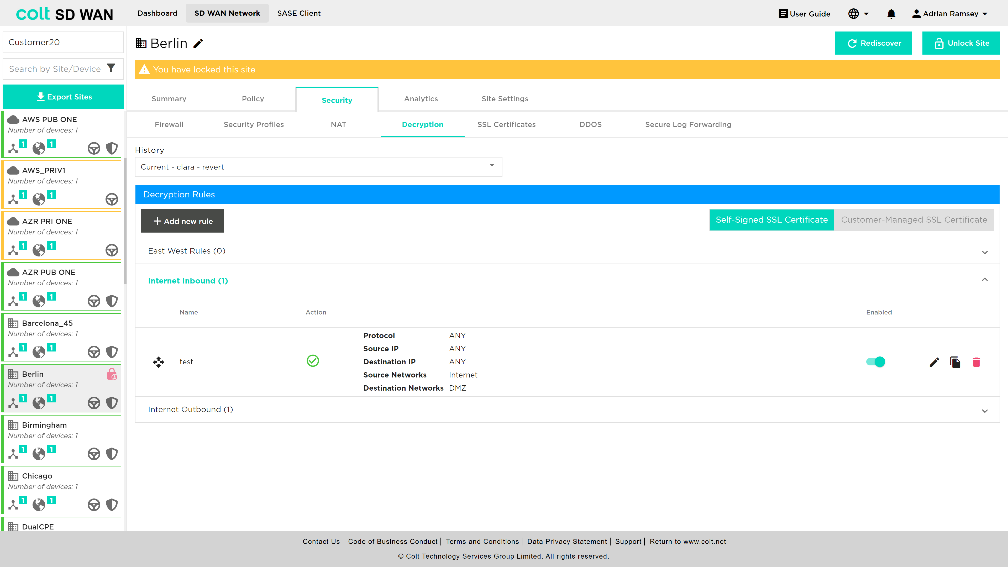
If a certificate is created, but no rules are added the default behaviour is that no decryption is performed.
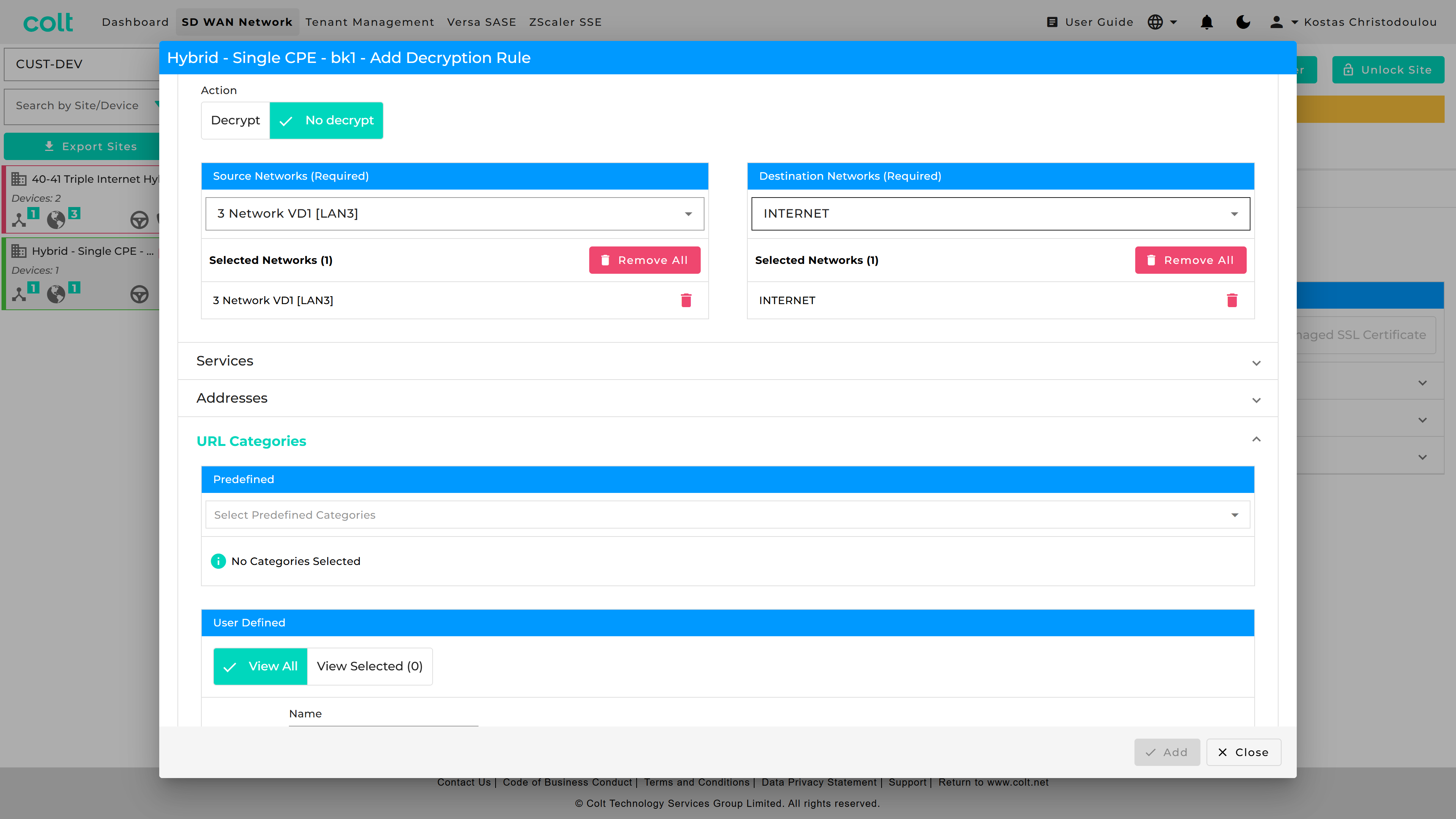
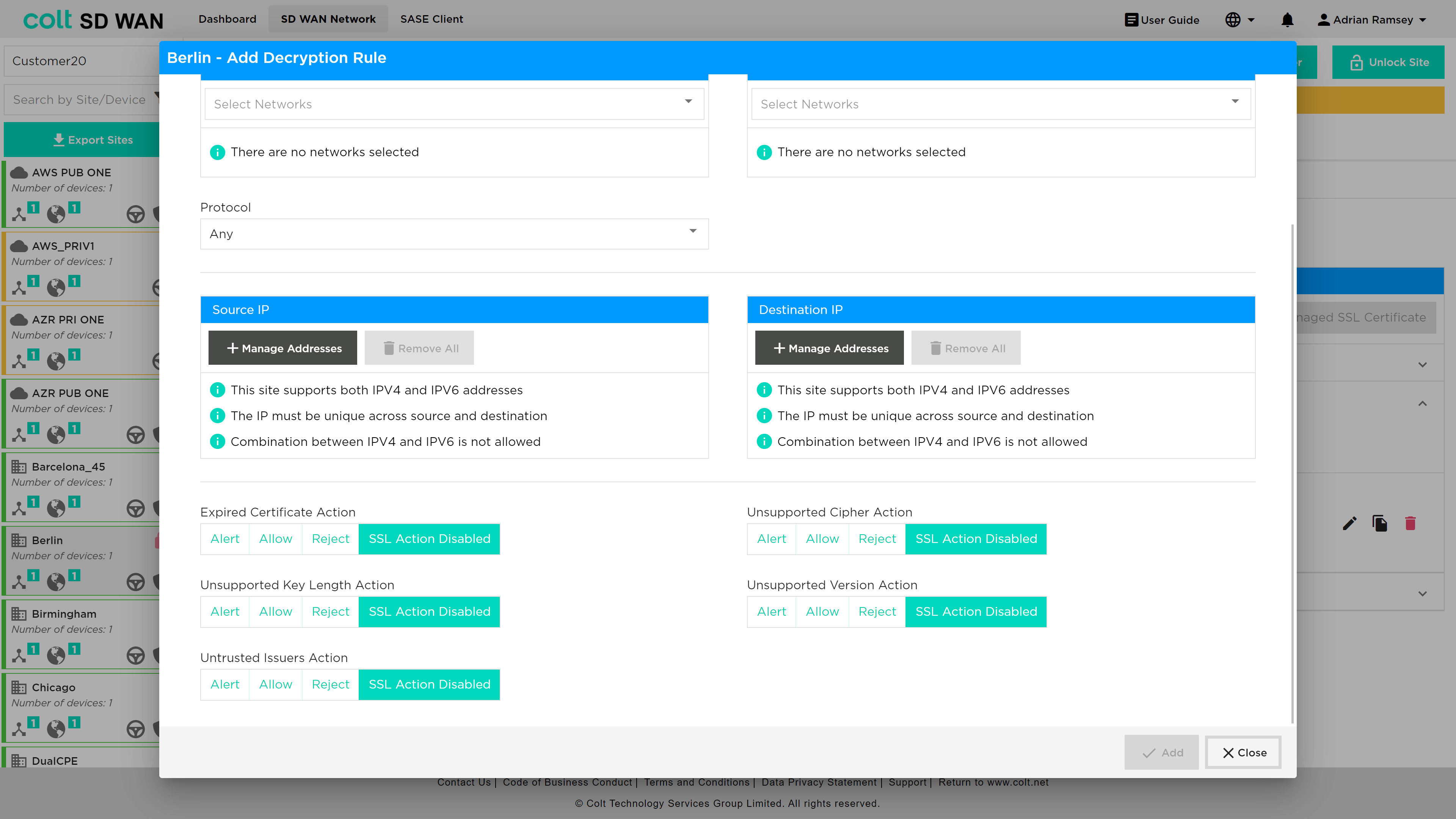
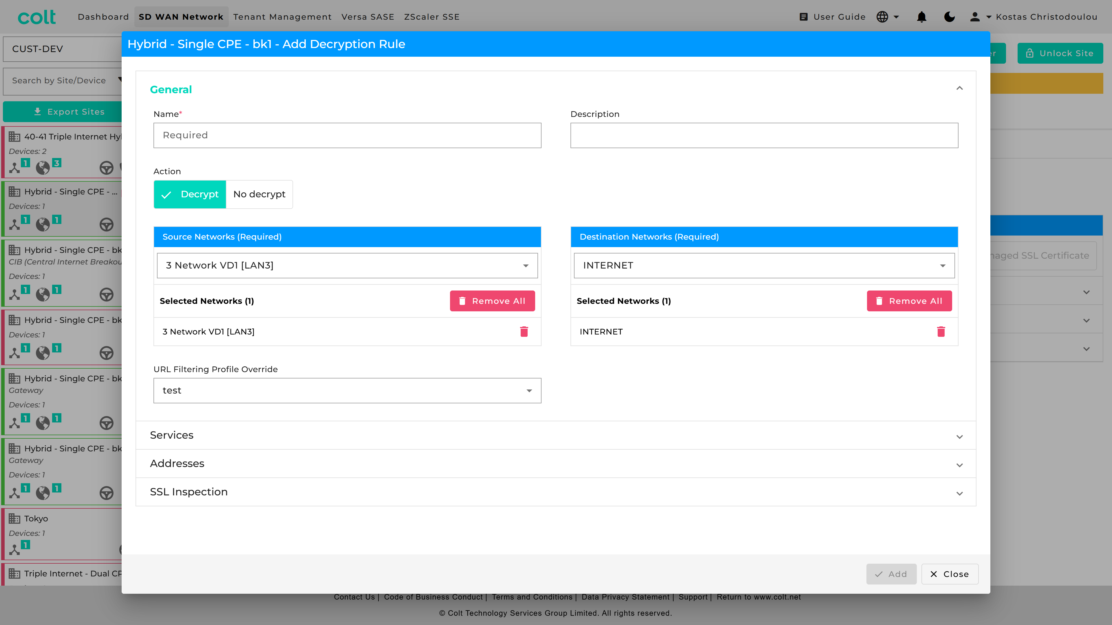
Rules can be added to match source and Source/Destination IP addresses and Services and to Decrypt or No-Decrypt. These rules can be applied to Self-Signed or Customer Managed SSL certificates. In addition the rule can be for outbound or inbound and applied to a specific protocol.
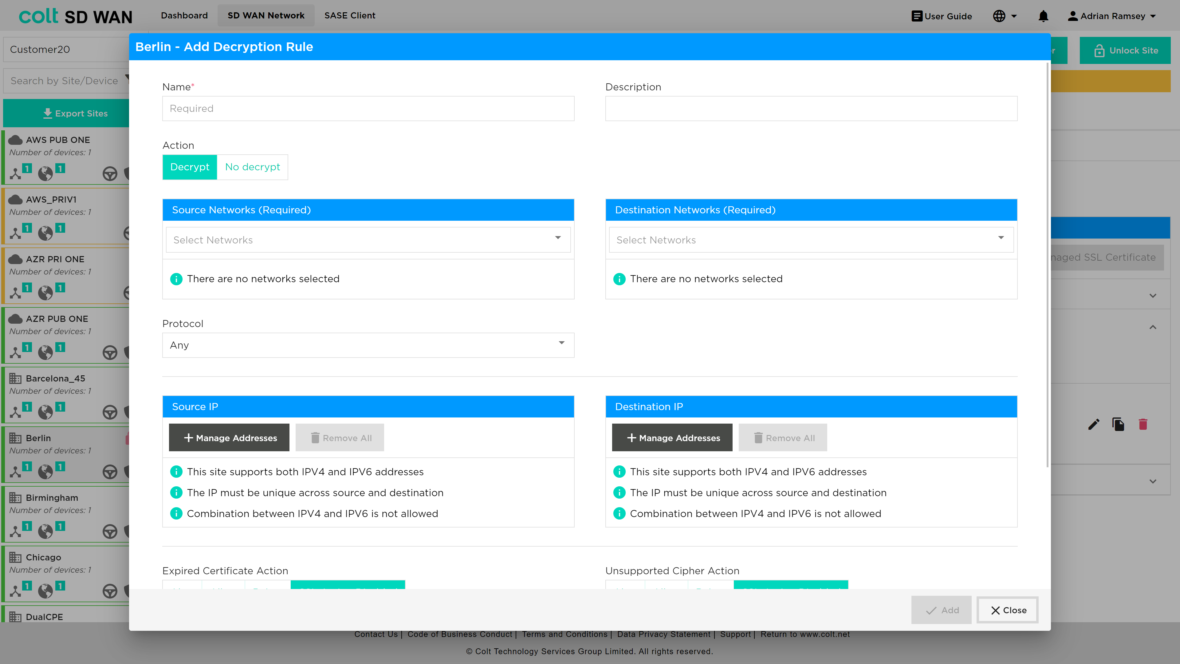
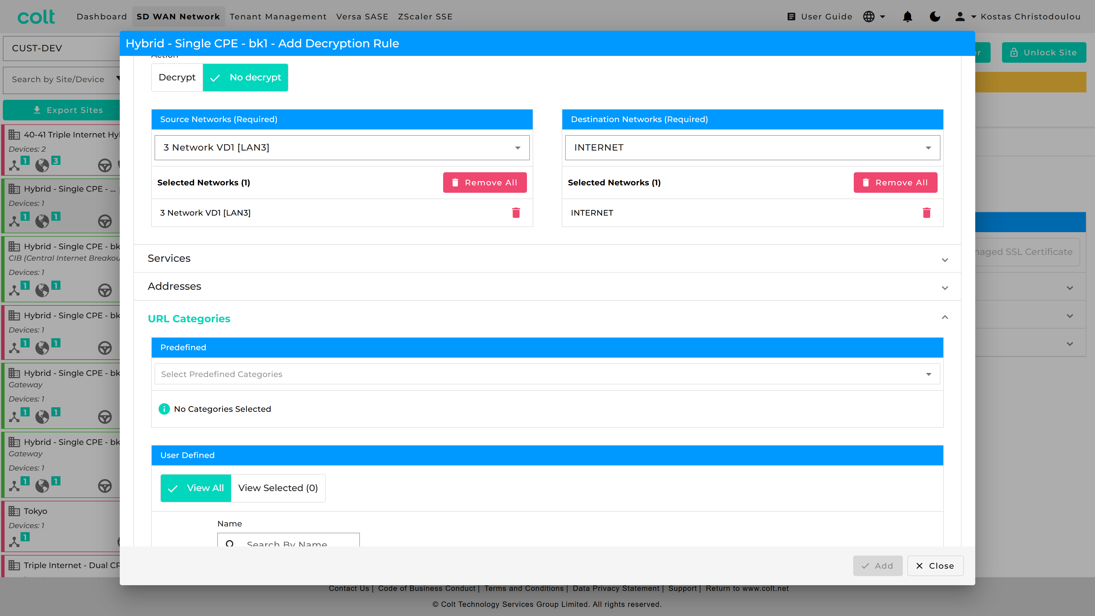
On top of this, Predfined and User Defined URL Categories are available for the Decryption rule that applies a "No-Decrypt" action.
In addition, to control and filtering of valid certificates, those that are invalid can be managed by selecting an action: Allow, Alert or Block. These actions are by default disabled as shown in the screenshot below.
| A Decryption rule with a Decrypt action (from LAN to INT) can reference a URL Filtering Profile in “URL Filtering Profile Override” to action the Decrypt Bypass. |
| A Decryption rule with a No decrypt action (from LAN to INT) can reference a Predefined or User Defined URL Categories Object. |
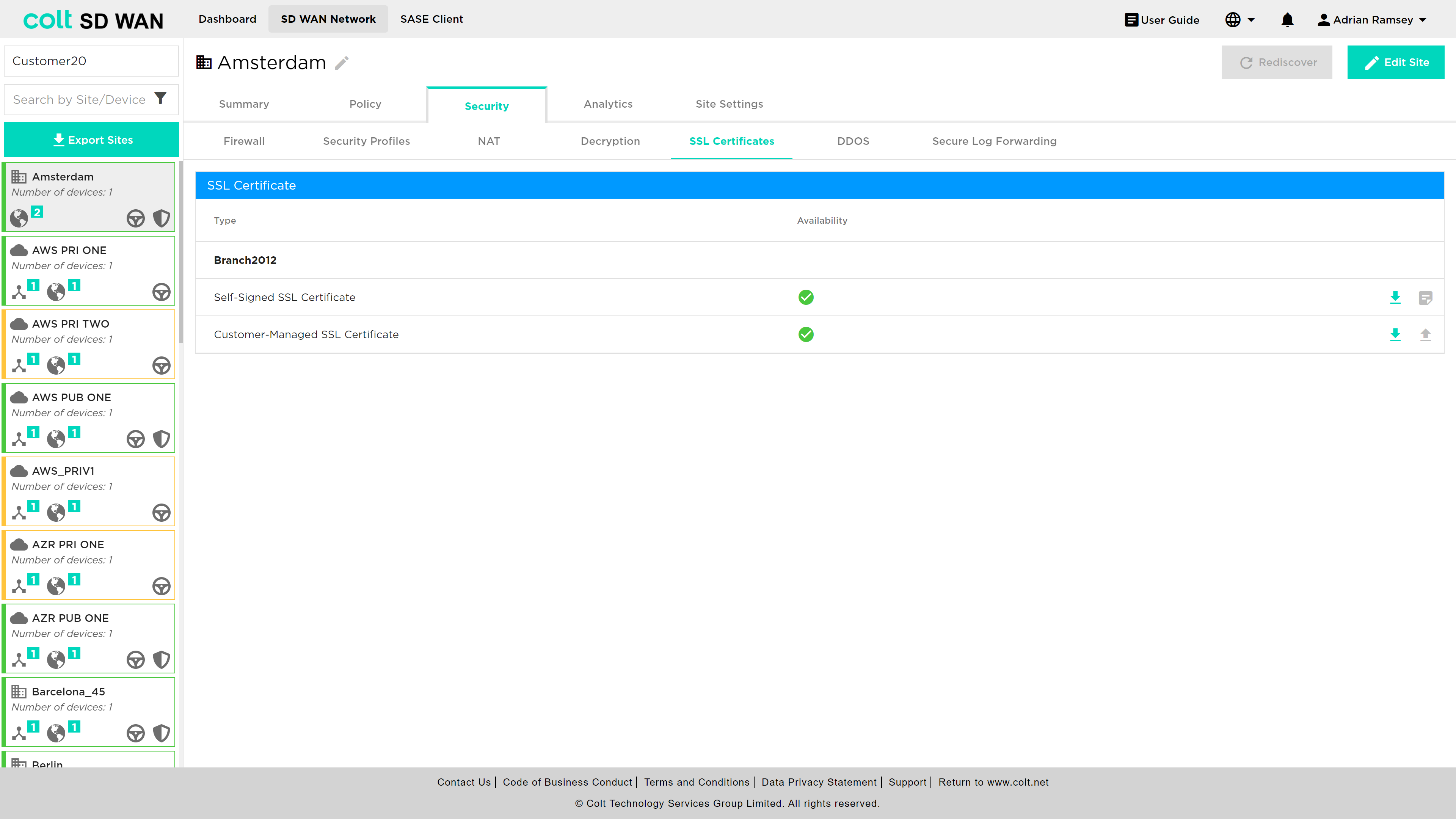
SSL Certificates
A customer can choose to generate self-signed certificates or upload their own CA certificates using the SSL Certificate menu option. Once selected the user will be able to see a list of current certificates and their status.
Self-signed certificates, which are time limited, will be displayed as a red cross under availability to indicate tha the certificate is either invalid or expired.
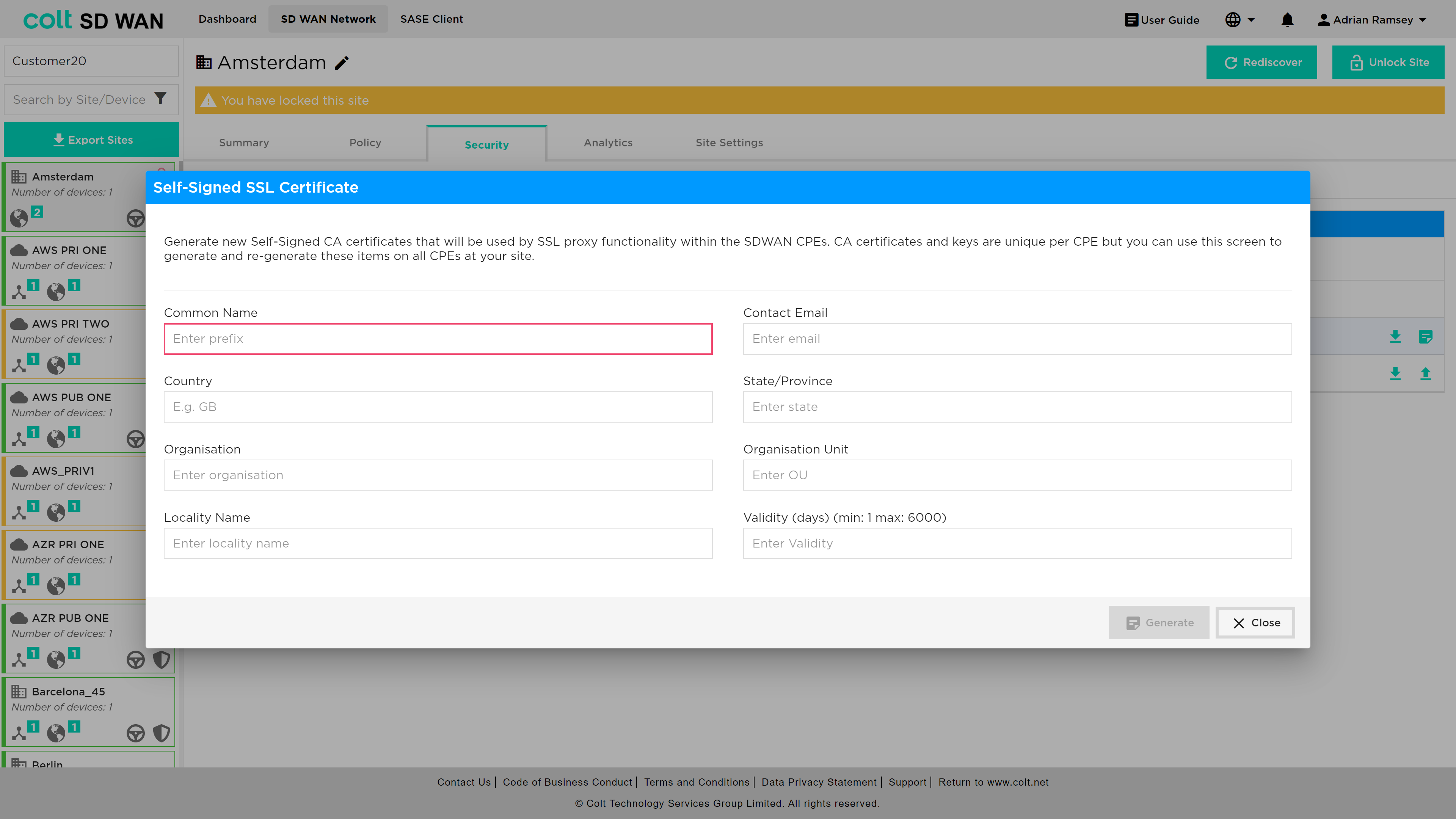
A new self-signed certificate can be generated by clicking on the icon on the far right of the “Self-Signed Certificate” line. This will reveal all the fields and conditions needed to generate a certificate, as shown below, including expiry conditions and key length.
|
Likewise, customer managed certificates can be uploaded by file or string and pasted into the certificate window as well as the Private key. Note that for SSL rules, these can’t be bulk copied between sites.
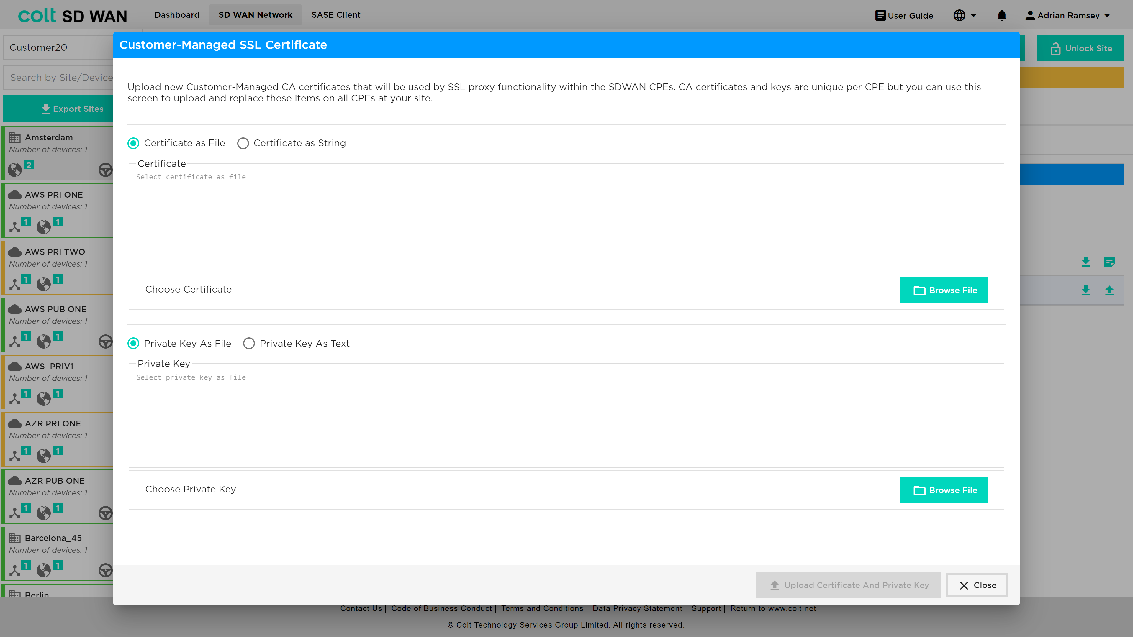
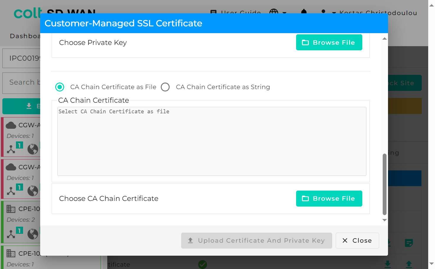
After upgrading VD to version 22, CA Chain certificates will also need to be uploaded as an extra security step that comes with this upgrade.
DDoS Management
| DDoS is not supported for Dual CPE in the SD WAN portal but is available as a bespoke solution. |
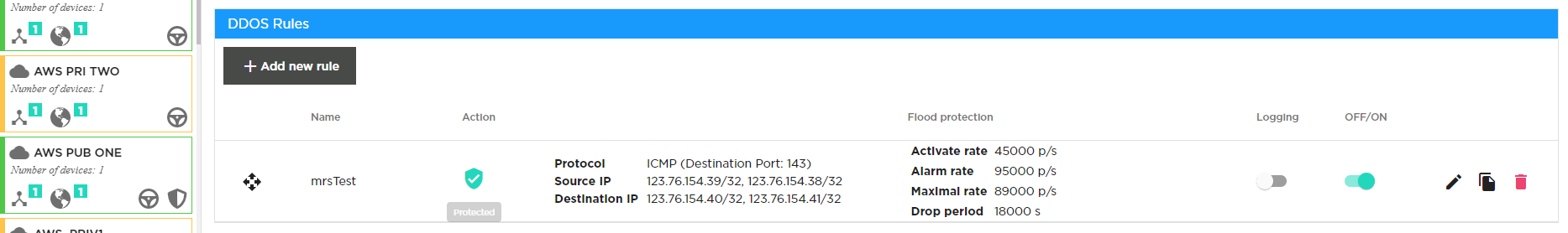
DDoS profiles can be created, edited and deleted. Logging can be enabled independently on each rule.
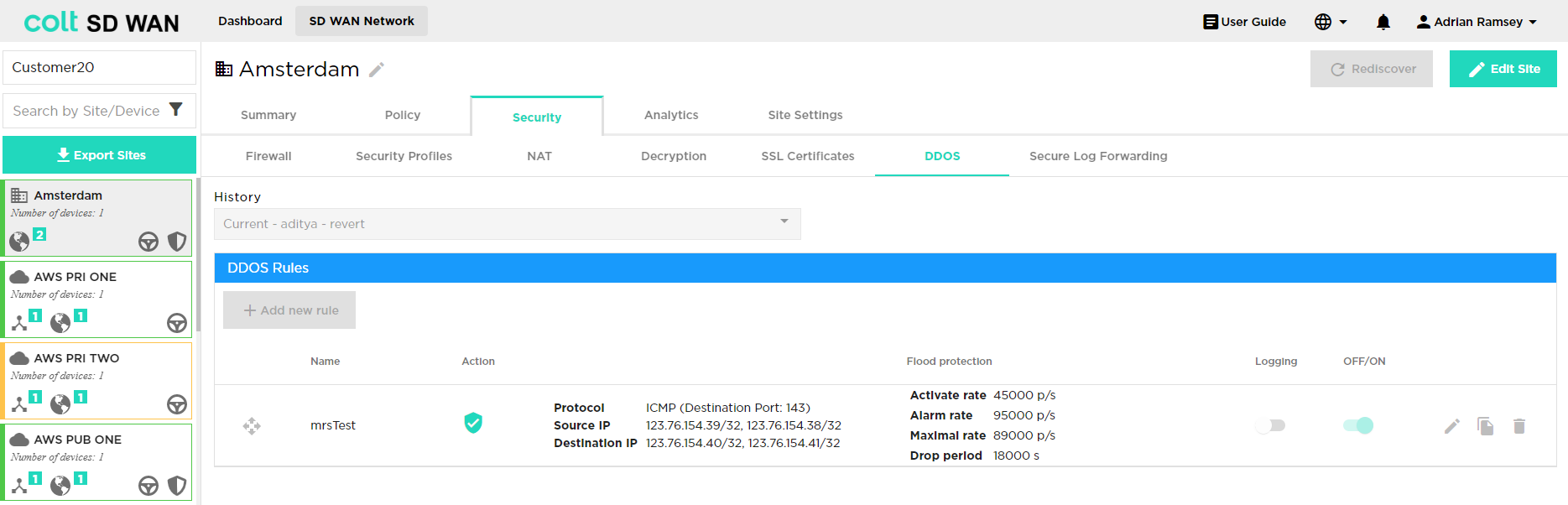
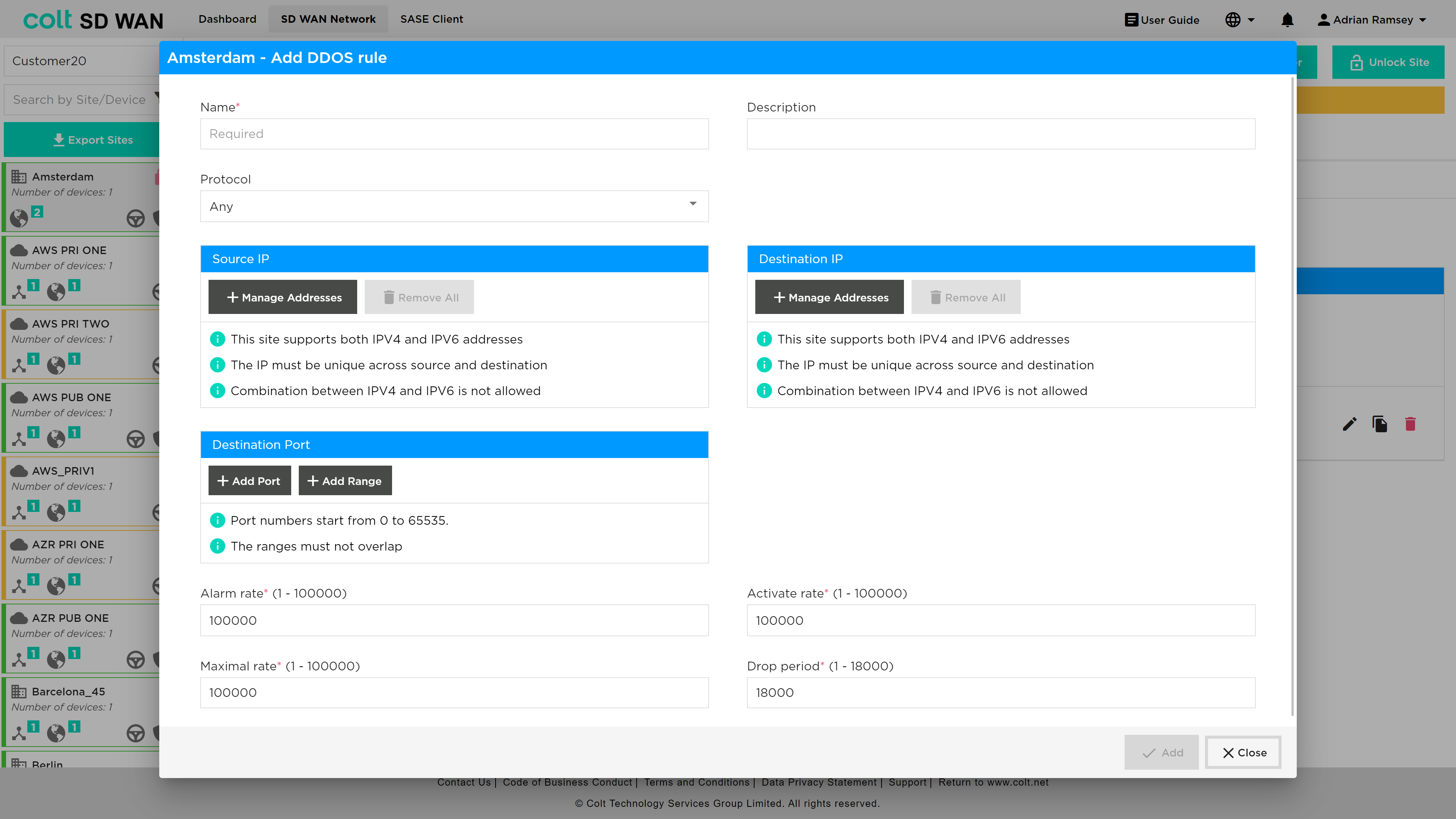
DDoS policies may be added by using the "+ Add new rule" button and the fields can be populated as shown below, with threshold value for activation, alarm and drop periods being defined by Portal users. The key fields are:
-
Name: Descriptive reference
-
Flood Protection Protocol: Identify which protocol DDoS protection rule applies too
-
Source IP: IP address and subnet DDoS traffic may originate (IPv4 or IPv6)
-
Destination IP: WAN IP or LAN/DMZ Address and Subnet being protected (IPv4 or IPv6)
-
Destination Port: Single or port range
-
Alarm Rate: The threshold rate at which to generate a DoS alarm, in packets per second.
-
Activate Rate: The threshold rate at which to activate a DoS response, in packets per second
-
Maximal Rate: The threshold rate of incoming packets, in packets per second. When this threshold is exceeded, all packets are dropped.
For an aggregate DDoS protection profile, this limit applies to all the traffic processed by the DDoS protection rule with which this DDoS protection profile is associated.
For a classified DDoS protection profile, this limit applies to the traffic on a classified basis (based on the source IP address, destination IP address, or both), for the traffic processed by the DDoS protection rule with which this DDoS protection profile is associated.
The “Add” button creates a rule which can be edited, and logging enabled.
DDoS logging can be enabled by slide button as shown below:
DDOS Log files can be searched for, by selecting the “Show DDOS logs” button to show a search by Day, Week, Month or Custom date range.
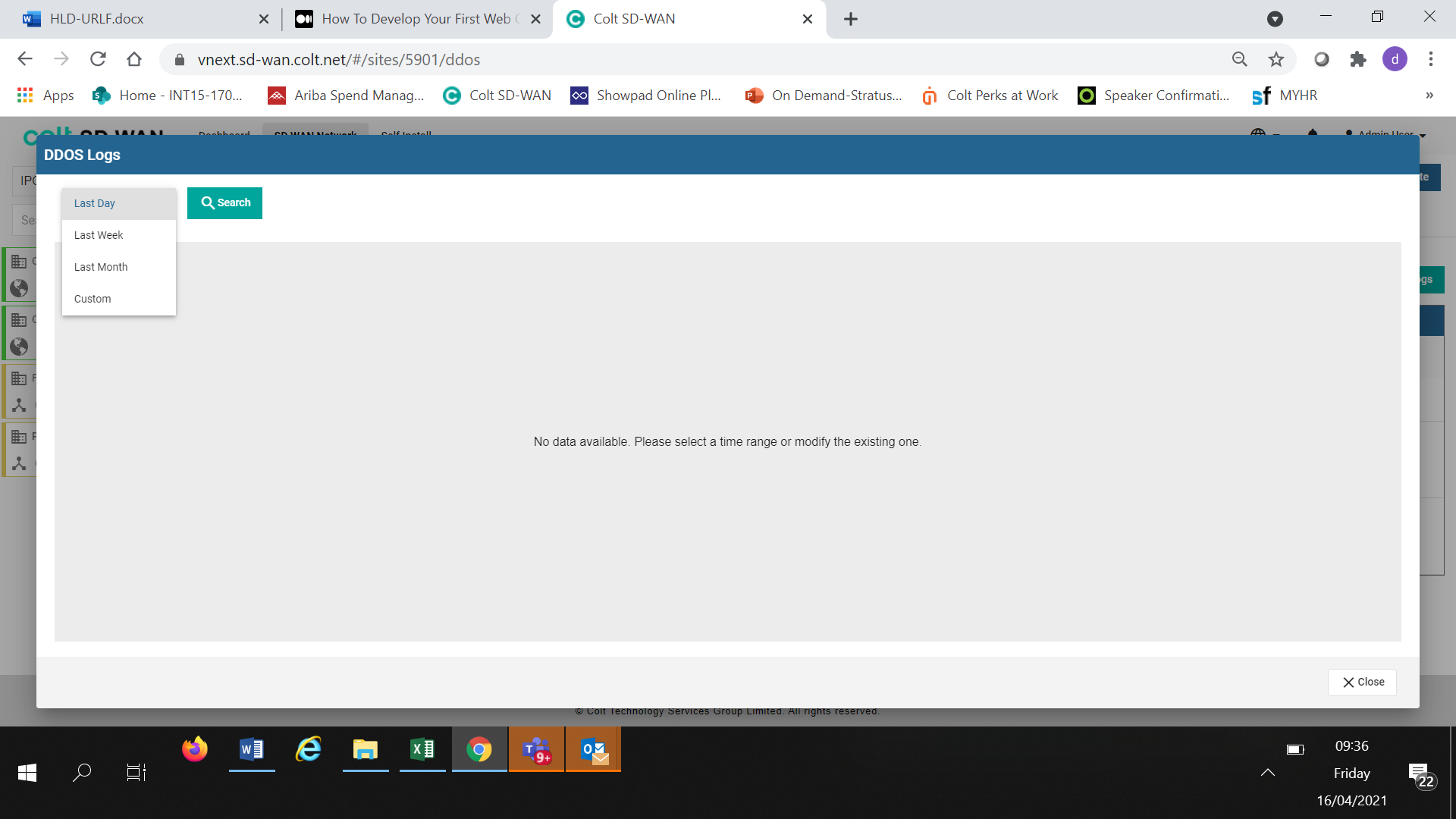
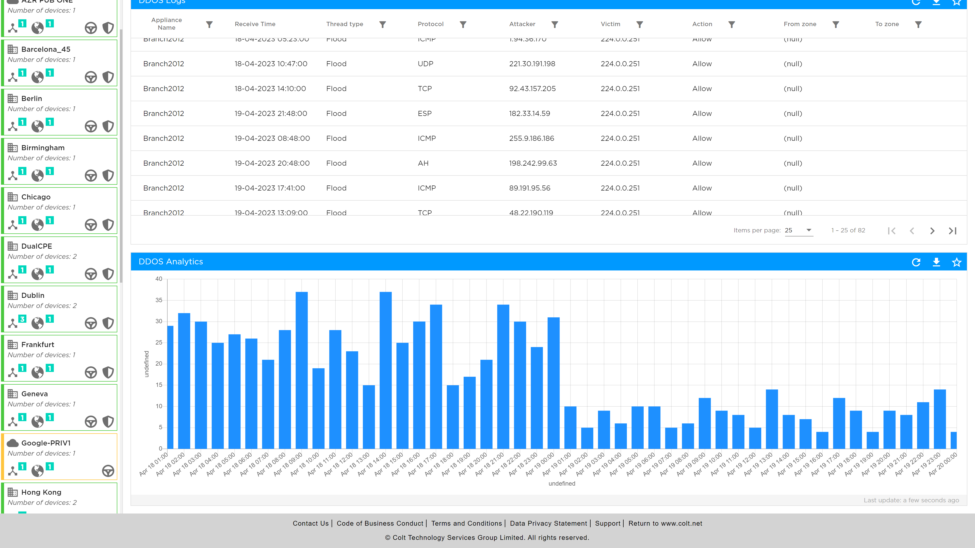
If log files are available they can be viewed in tabular form or downloaded as a CSV file. The tabular view shows the site name, date type of attack/protocol, attacked IP address and action.
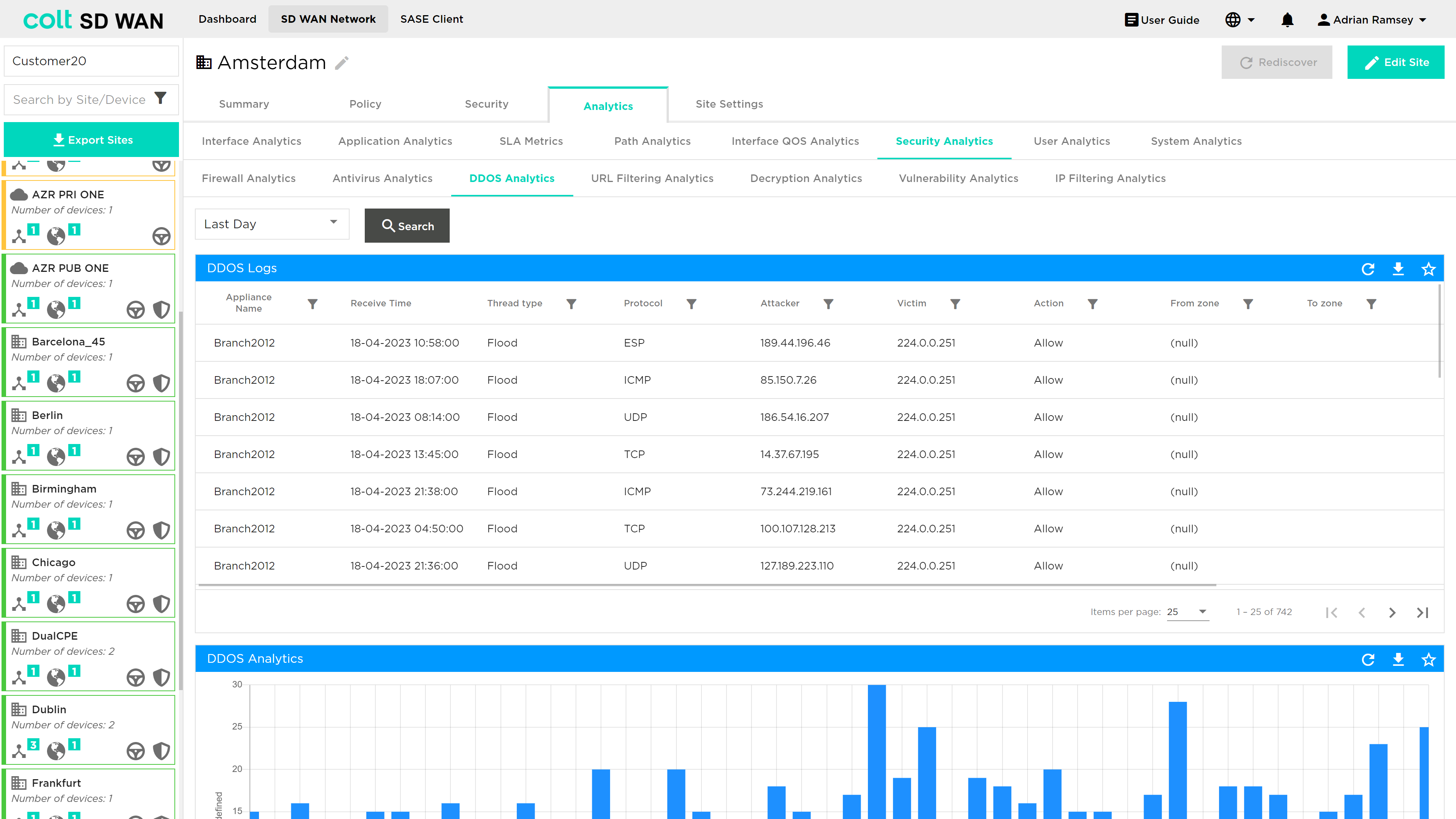
The Log files can also be viewed in Chart form by selecting the Chart View option.
Secure Log Forwarding
There is a growing demand for streaming logs to third party collectors in many products. For SD WAN, customers subscribing to firewall features may require firewall service logs for audit and compliance perspective. As such, this feature allows CPE firewall log delivery to a Third Party collector for a branch site.
| For Secure Log Forwarding we are not supporting the collector being hosted in the Internet. If the customer site has local internet breakout enabled, to ensure logs are forwarded securely, it is highly recommended to configure a deny firewall rule before any existing rules and also should match LAN-Zone(s) and the destination log collector IP. See the portal screenshots on the next page: |
| When configuring collectors for Secure Log Forwarding (SLF) and NetFlow on the same server, please make sure that the combination of Destination Address and Destination Port is unique for each collector. This means you cannot use the same IP address and port combination for both SLF and NetFlow collectors. |
The rule should be established as below:
To configure CPE log forwarding for a specific site, first the customer needs to select the ‘Security’ tab in the main menu and then underneath this, the ‘Secure Log Forwarding’ tab as shown below.
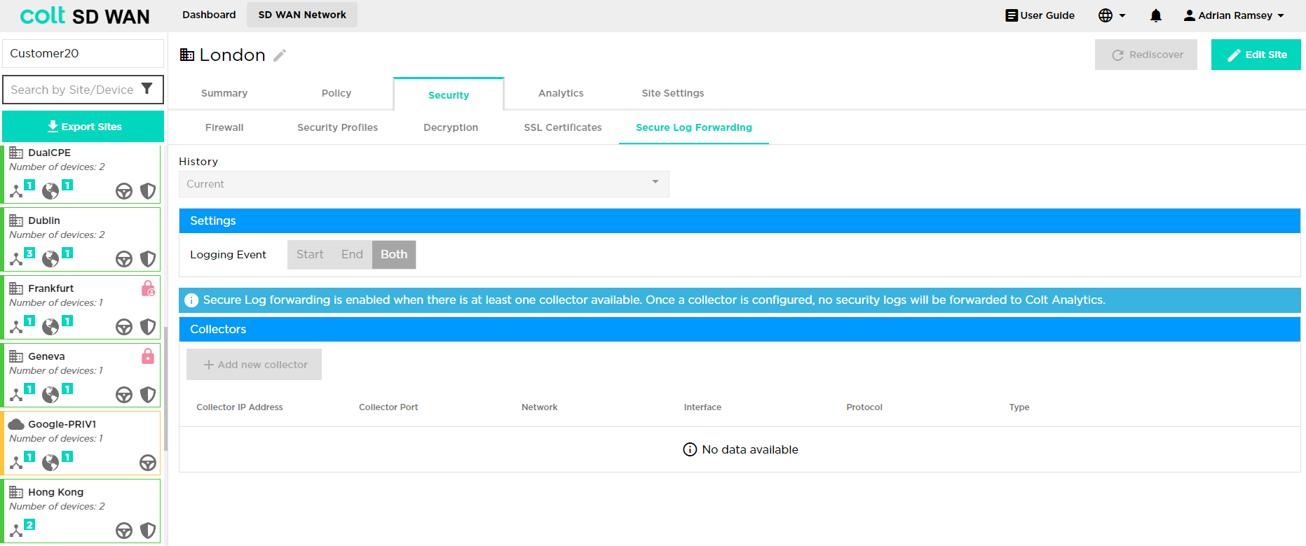
The customer will need to take the following steps to configure CPE log forwarding:
-
Click on the ‘Edit Site’ button at the top right of the screen
Input the various attributes associated:
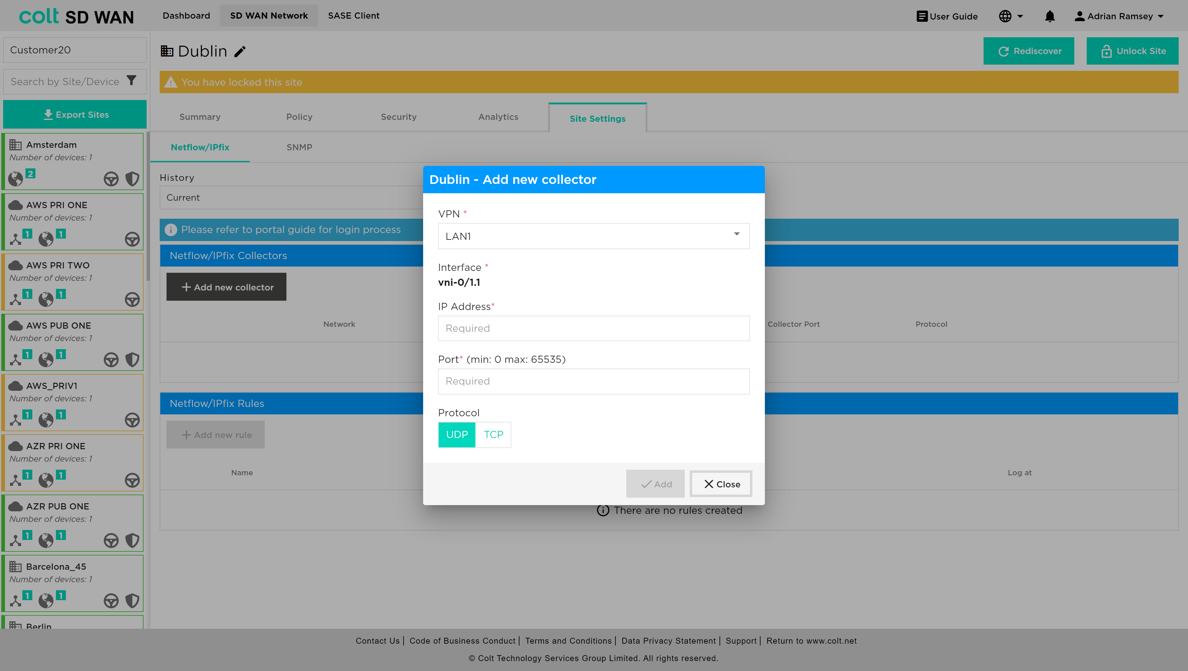
Firstly click ‘Add new collector’ – the following input dialogue opens:
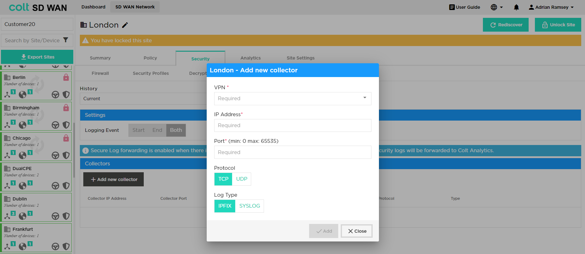
The following data needs then to be inputted by the user:
-
VPN / Routing instance: The network needs to be defined i.e. LAN1, LAN2
-
IP Address: The collector server IPv4 address
-
Port: The destination port which will be used to establish a session
-
Protocol: Select ‘TCP’ or ‘UDP’. Note that With Protocol UDP, only one collector is allowed. With TCP, customer can configure two collectors. If two collectors are chosen then the user should select one as a primary and an additional option is provided to suspend the backup collector if preferred
-
Log type: Select whether ‘IPFix’ or ‘Syslog’ as appropriate
After this then the logging event settings can be defined: Start / End / Both. Once this is selected then the ‘Enable Secure Log Forwarding’ needs to be pressed and the settings saved to enable the feature.
By default this profile is then applied to all firewall rules and security features that have logging enabled. Additional firewall rules and security features can be added and will have the Secure Log Forwarding profile added by default if the user selects logging when the rule is established.
Versa SASE (Secure Access Servide Edge)
We are introducing Versa SASE - Secure Access Service Edge (SASE) integration into the SDWAN Portal. This integration standardizes the connectivity between Colt Versa SDWAN sites and the SASE services offered by Versa. SASE is a network security feature, that has cloud-based security appliances and streamlined traffic routing to SASE Gateways through the public Internet. This feature ensures a safe and secure online experience, by offering:
-
Comprehensive Security Features: SASE delivers a comprehensive set of security features for internet, cloud services, and private applications.
-
Access Control: Manage and control user access to ensure only authorized users gain entry.
-
Threat Protection: Guards against online threats, providing protection from malicious activities and cyberattacks.
-
Data Security: Ensures the confidentiality and safety of your data.
-
Security Monitoring: Monitors online activities, offering real-time insights and alerts for suspicious events.
-
Acceptable Use Control: Enforces policies regarding internet and application usage to align with organizational rules.
With the growing importance of SASE as a service choice for our customers, it’s important that your SDWAN Portal reflects the SASE characteristics.
The SDWAN Portal has been updated to support this integration. It can now offer the capability to:
-
Identify SASE-Enabled Sites: Easily discern which sites have SASE capability.
-
Tunnel Visibility: The portal displays SASE tunnel details and their status, providing a comprehensive overview of your network’s security infrastructure.
-
CLI Commands: A console interface allows you to execute CLI commands associated with your SASE interfaces.
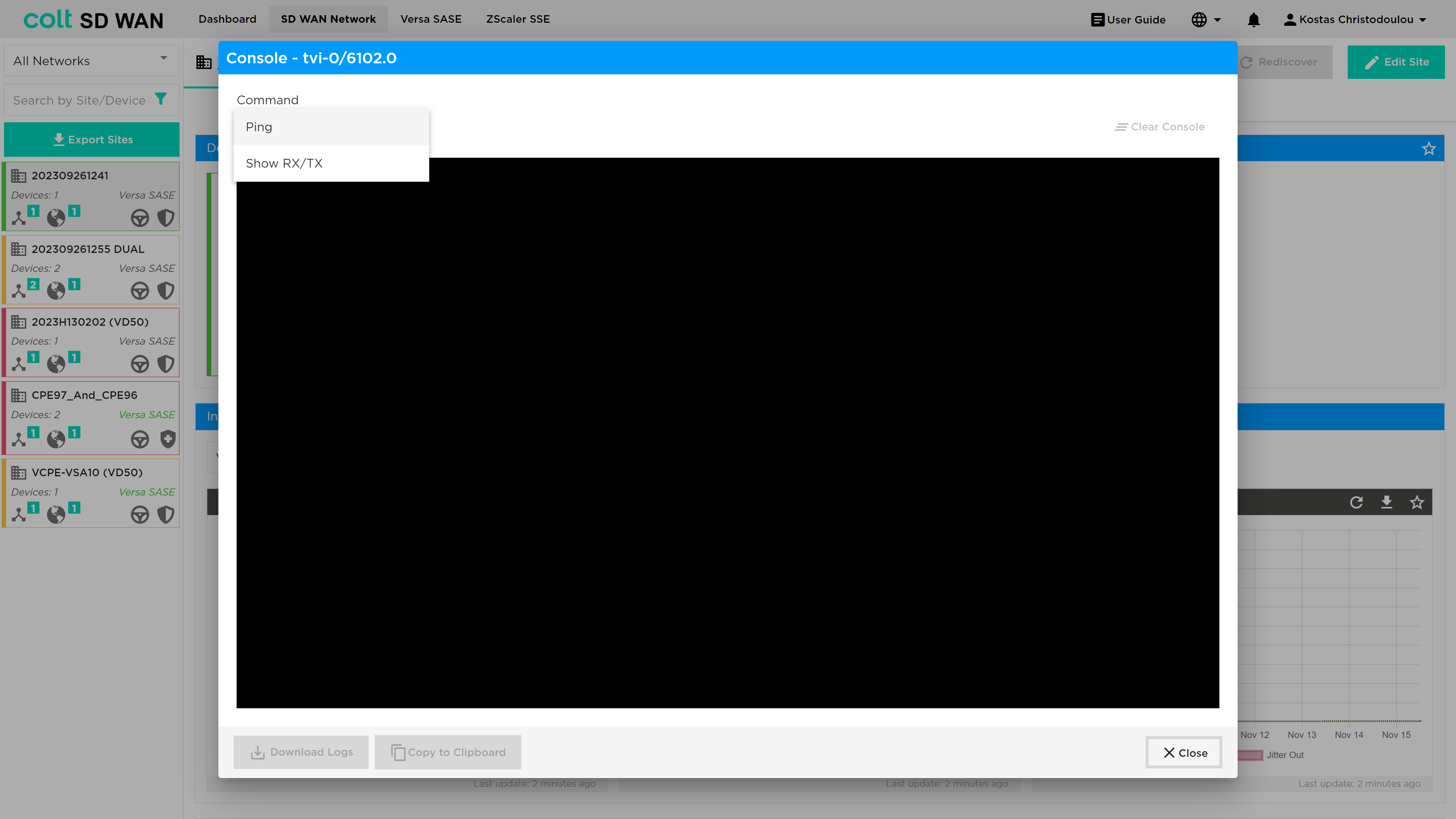
-
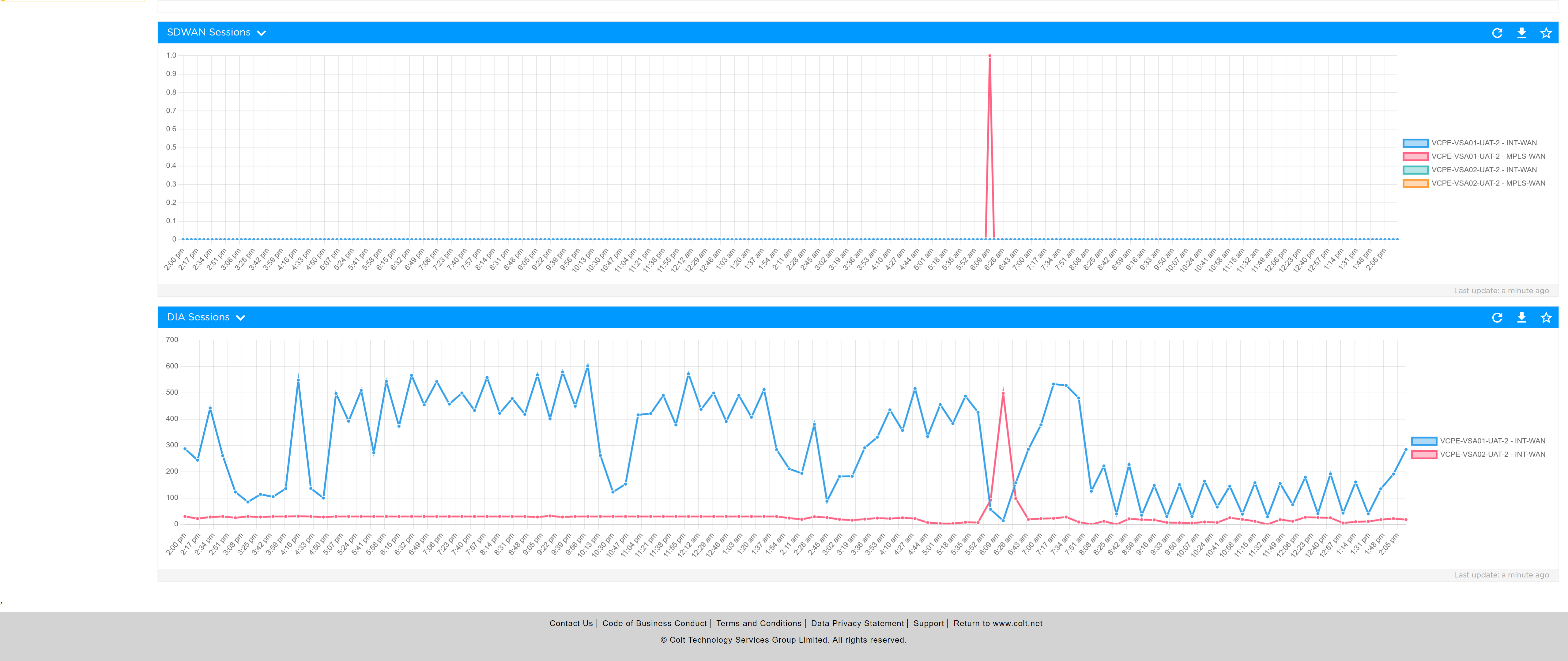
Analytics View: Insights on DIA (Direct Internet Access)
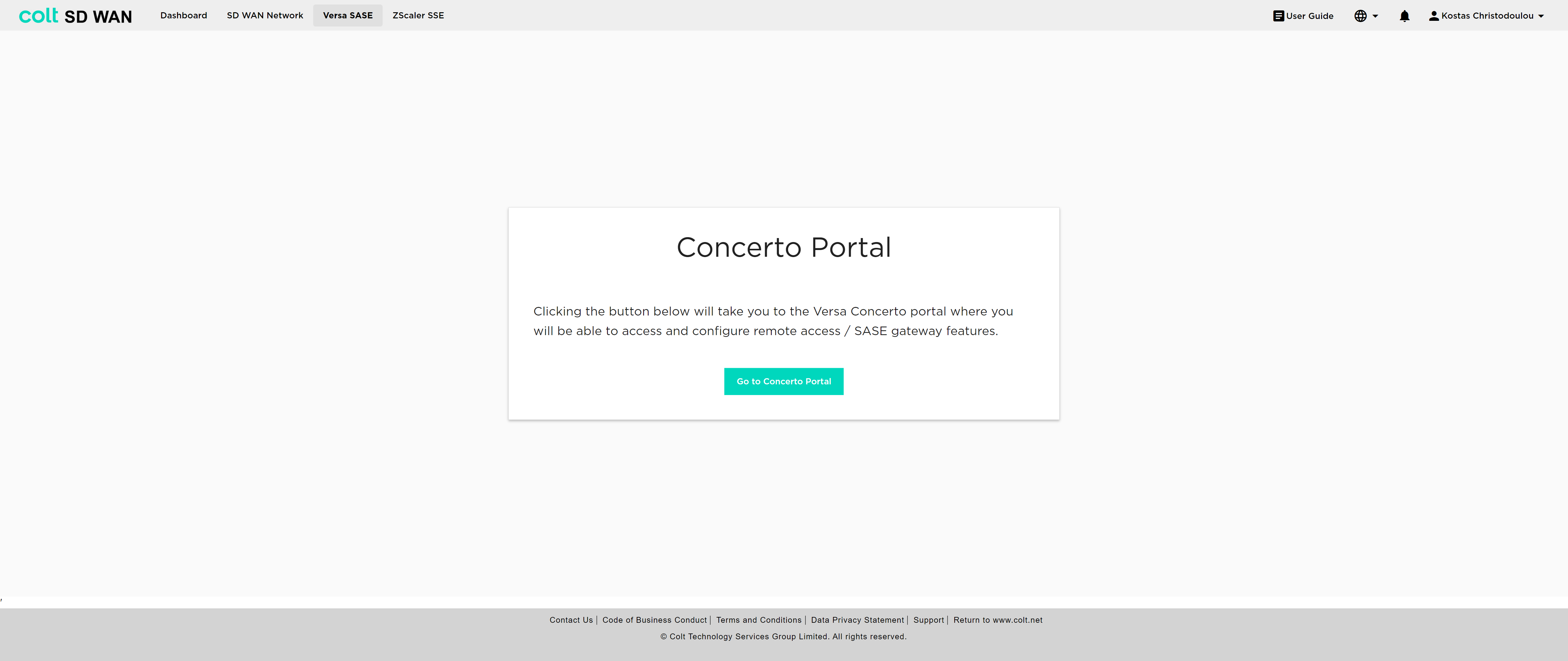
The user must navigate to the Versa SASE button from the ribbon, which takes them to the Concerto portal, in order to configure the desired policies.
For the configuration the following principles apply:
-
2 IPsec tunnels, Primary and Backup, are necessary.
-
In single CPE scenarios SASE can be enabled if at least 1 IPsec tunnel is up.
-
In dual CPE scenarios SASE can be enabled if only 1 IPSec tunnel is up in the primary CPE.
-
Traffic is only available over Internet interfaces, not MPLS.
-
All internet-based traffic is forwarded through the SASE tunnel by default, but users still have the option to define specific traffic flows to go through the LIB or CIB.
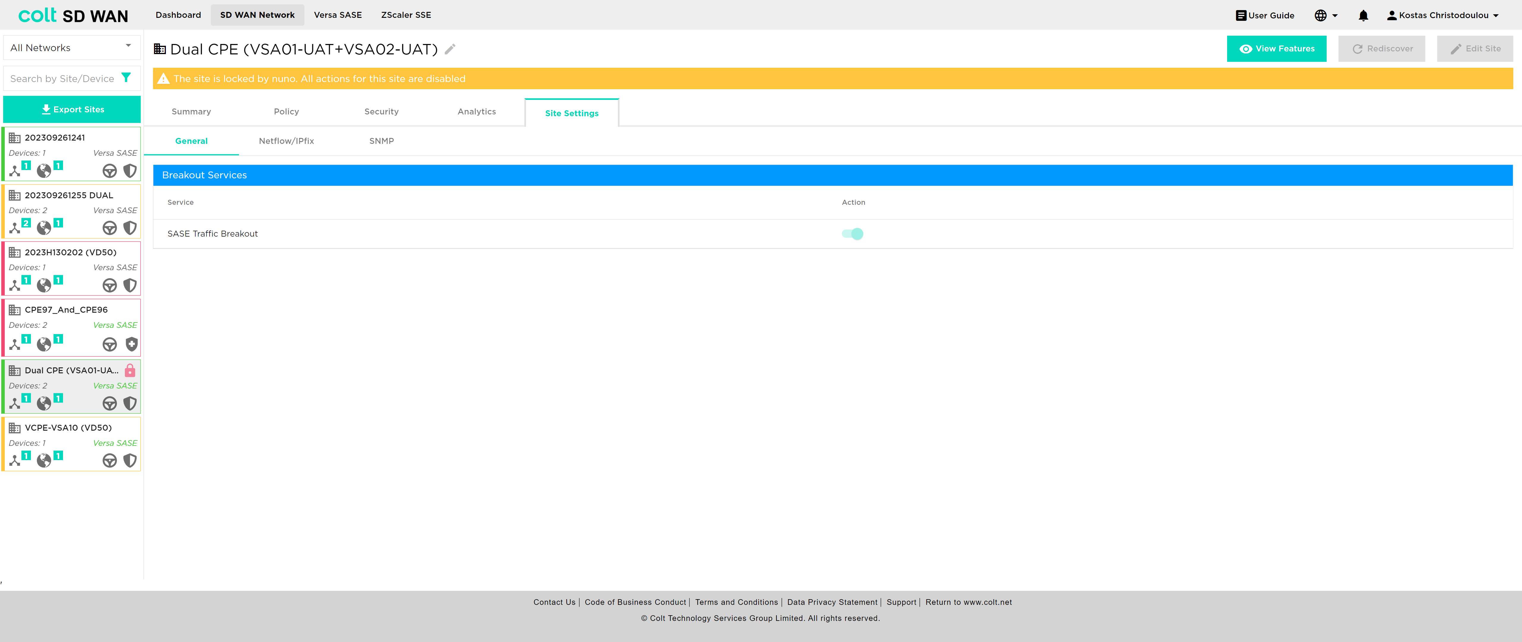
After Colt configures the tunnels for SASE in the SD WAN portal, the user can refresh the page in order to see the updated status of the tunnels and also use the Versa SASE breakout button to activate/deactivate SASE.
| This button does not affect the tunnels, but only dictates the traffic. The button is located under the “Site Settings” tab. |
In addition, it’s essential to understand how traffic behaves when LIB or CIB is activated in the context of Versa SASE, specifically LIB, CIB and Versa SASE: When LIB is enabled for a site along with SASE, traffic by default will always be sent over the preferred SASE GW. In the event that the routes from SASE GW are not available, traffic will be sent over LIB. If CIB is also enabled for customers, there will be an additional backup default route. However, for the traffic to reach the Internet via LIB or CIB, the users need to configure the appropriate firewall and Internet traffic steering rules via the SD WAN portal. Last, if the user wishes to remove SASE, it´s recommendable that LIB or CIB are active with the appropriate Firewall rules in order to avoid potential issues on the traffic.
| If there is an app steering policy created, then the above default behaviour can be overriden and the path followed can be the one set via the policy. |
ZScaler SSE (Security Service Edge)
We are introducing Zscaler SSE integration into the SDWAN portal that brings in a significant enhancement, enabling the integration of SDWAN with Zscaler’s Security Service Edge solution. SSE, is a set of comprehensive security features designed to safeguard your access to the internet, cloud services, and private applications. These features ensure a safe and secure online experience, by offering:
-
Access Control: SSE helps manage who can access what, ensuring that only authorized users get in.
-
Threat Protection: It stands guard against online threats, protecting you from malicious activities and cyberattacks.
-
Data Security: SSE keeps your data safe. Your information remains confidential.
-
Security Monitoring: It keeps an eye on your online activities, providing real-time insights and alerts if something suspicious is happening.
-
Acceptable Use Control: SSE helps enforce policies about how the internet and applications can be used, making sure everything is in line with your organization’s rules.
Zscaler, a cloud-based security-as-a-service offering requires the establishment of GRE tunnels between Versa CPE and Zscaler (Zen) Nodes to efficiently route customer traffic through its cloud-based security appliances. To meet this demand and reflect the crucial tunnel details on the SDWAN Portal, we’ve introduced several key capabilities:
-
Identify Zscaler SSE sites: Easily discern which sites have Zscaler SSE capability.
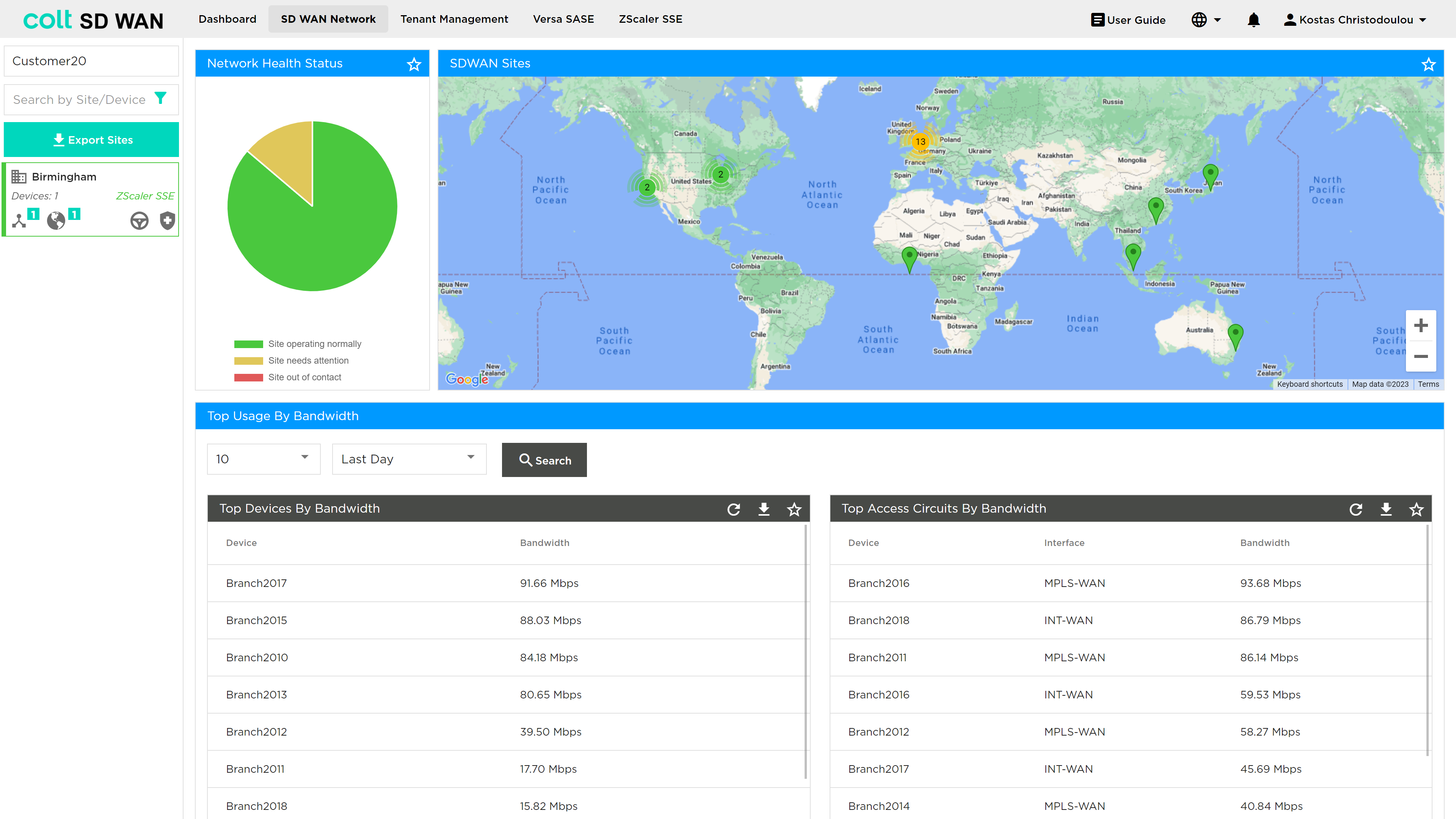
-
Tunnel Visibility: The portal displays Zscaler tunnel details and their status, providing a comprehensive overview of your network’s security infrastructure.
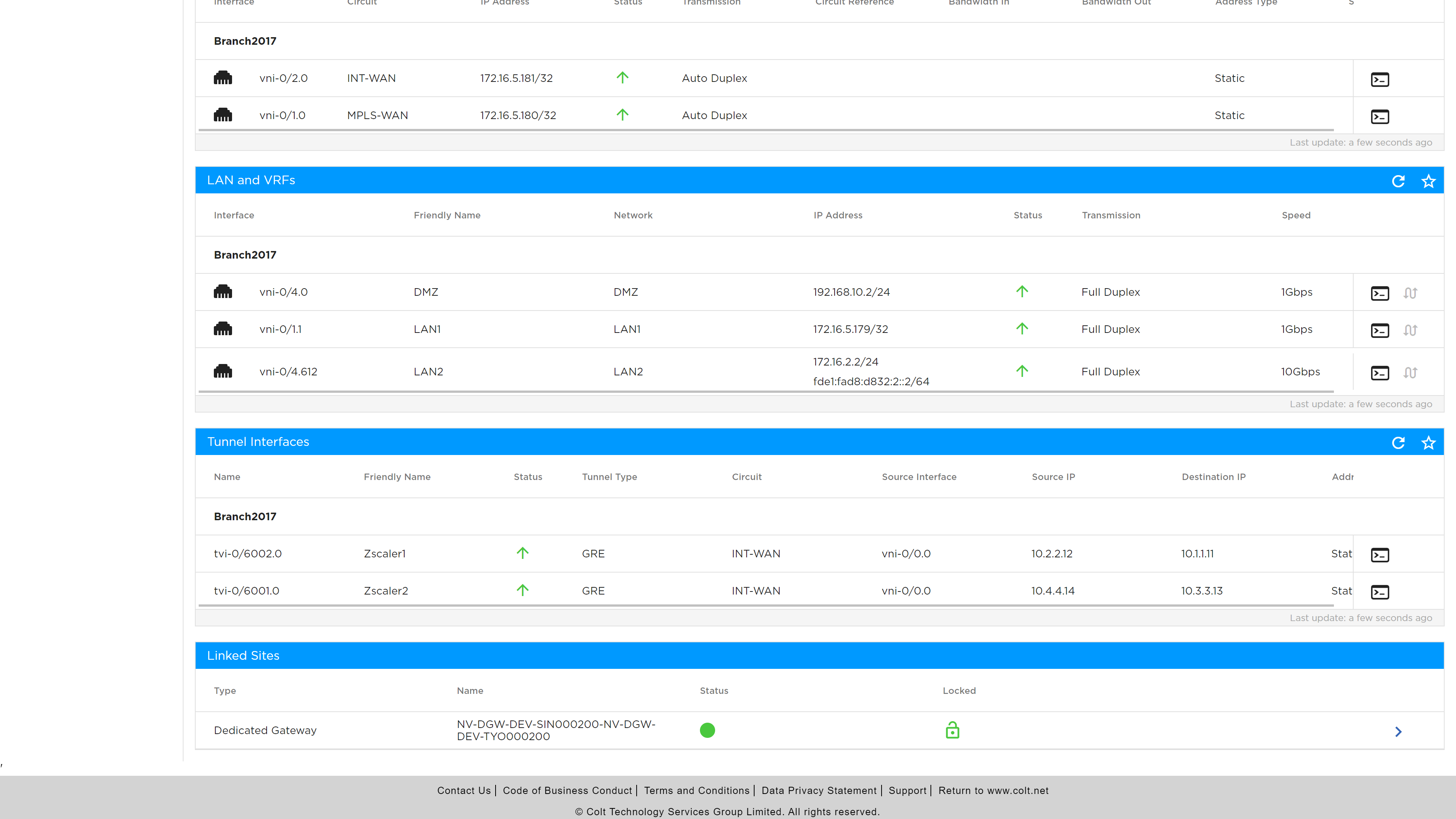
-
CLI Commands: A console interface allows you to execute CLI commands associated with your SSE interfaces.
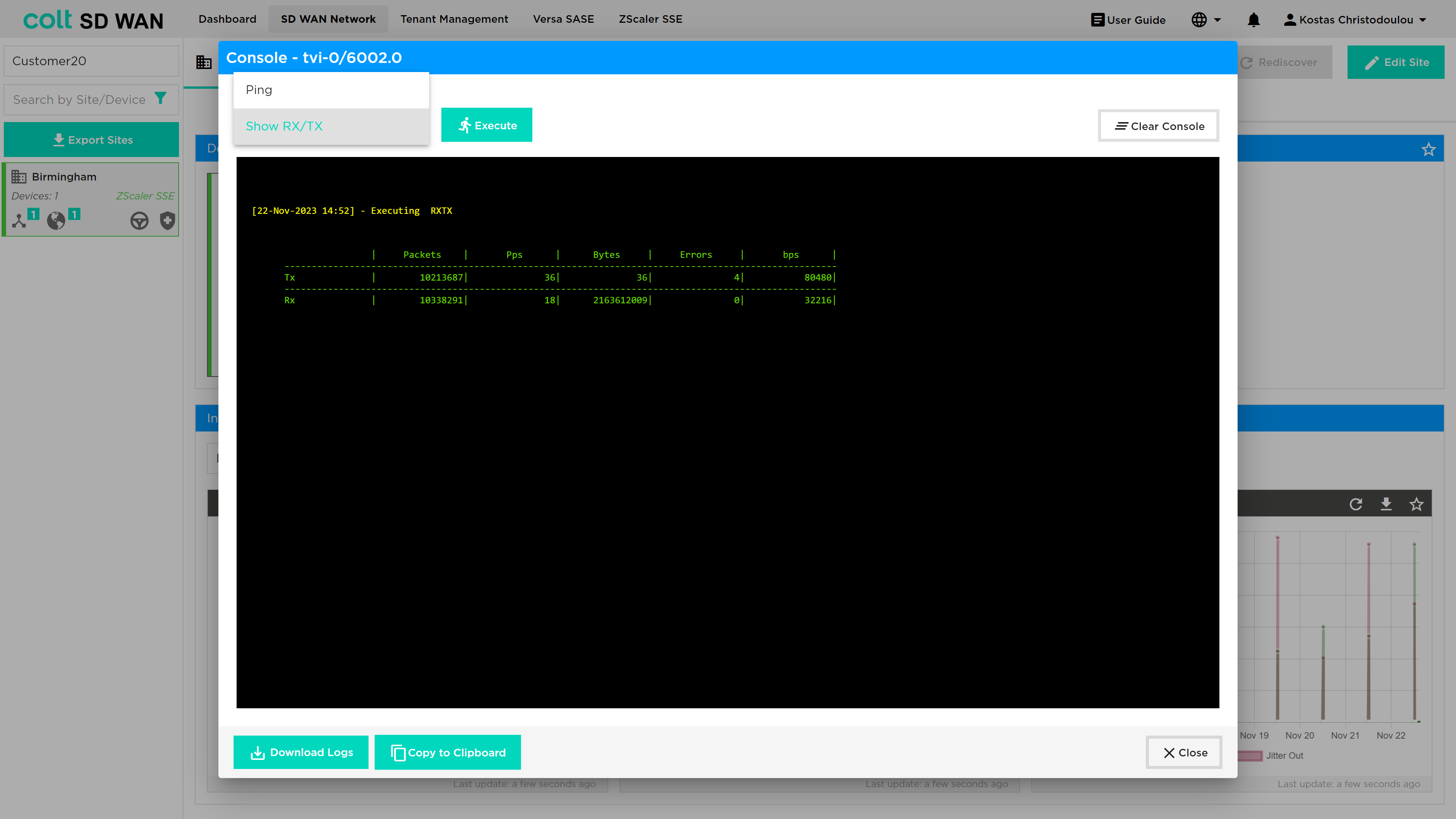
-
Analytics View: Insights on DIA (Direct Internet Access)
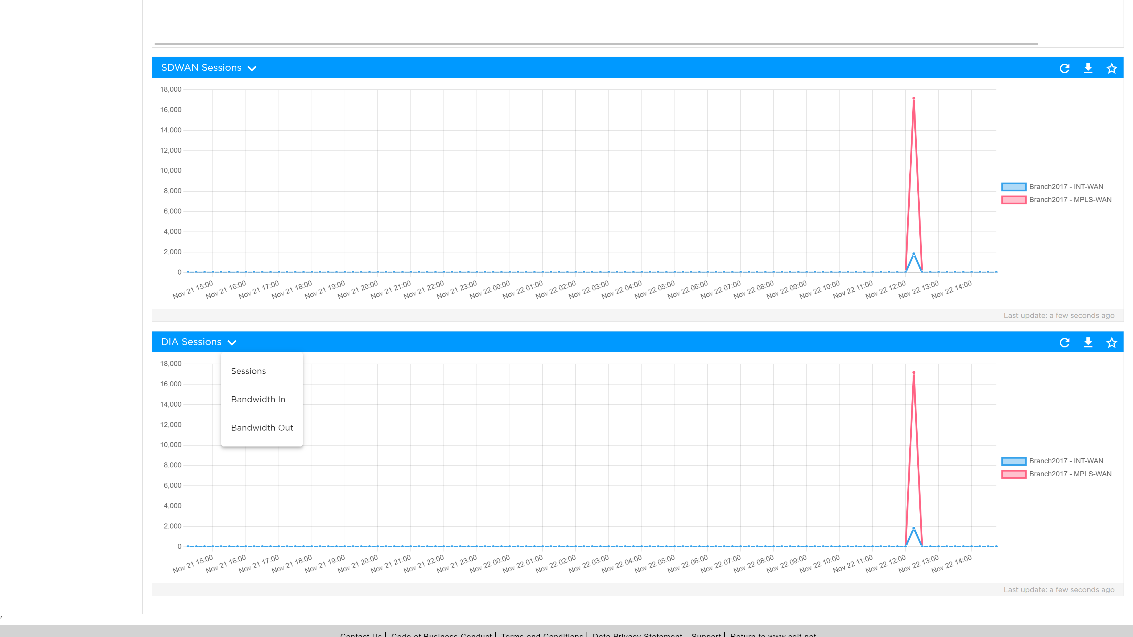
The user must navigate to the ZScaler SSE button from the ribbon, which takes them to the ZScaler portal, in order to configure the desired policies.
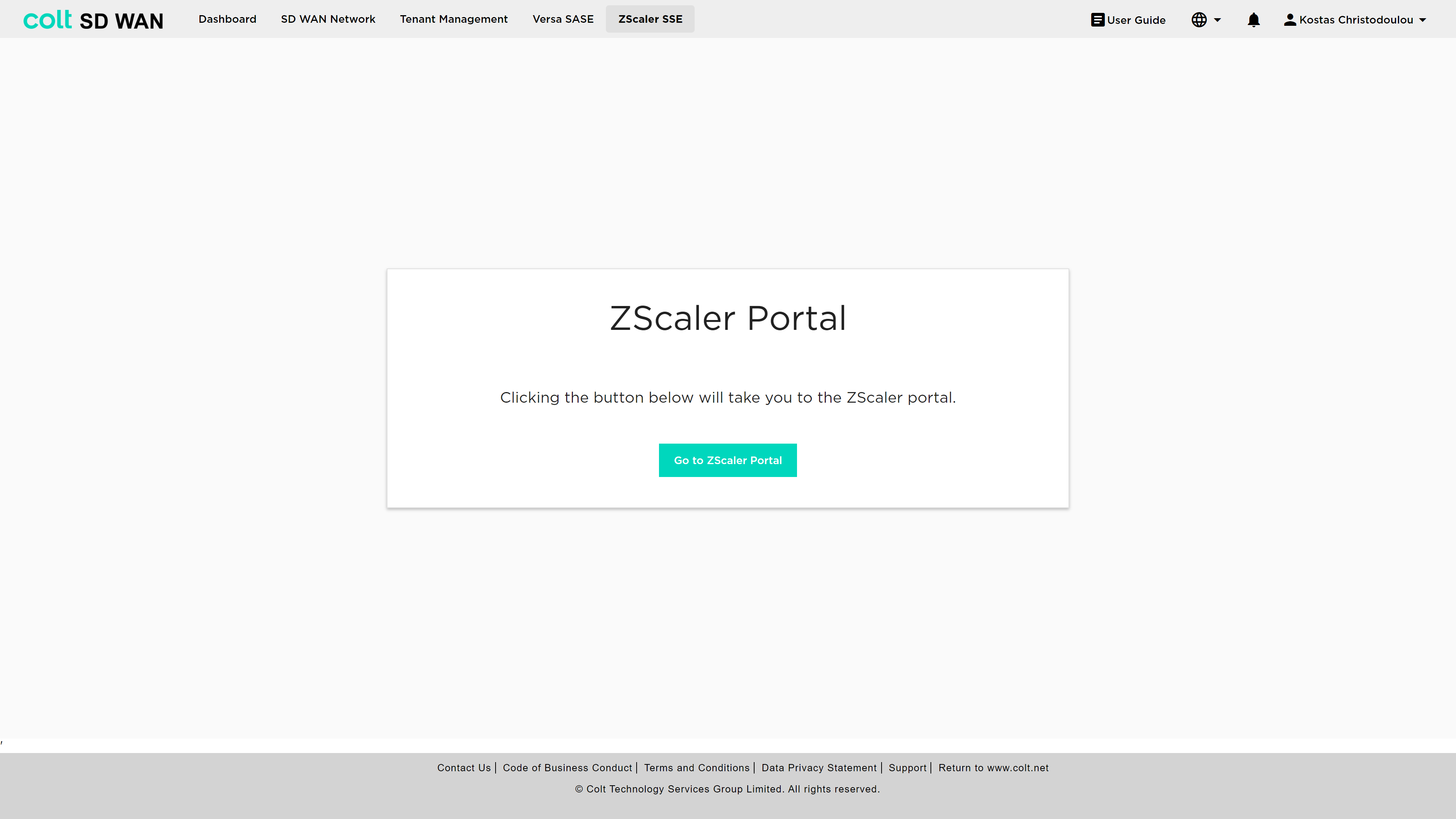
For the configuration the following principles apply:
-
2 GRE tunnels, Primary and Backup, are necessary.
-
ZEN node traffic is only available over Internet interfaces, not MPLS.
-
BGP routing into the customer LAN is possible, involving the redistribution of static routes.
-
All internet-based traffic is forwarded through the tunnel by default, but users still have the option to define specific traffic flows via LIB.
After Colt configures the tunnel for SSE in the SD WAN portal, the customer can use the Zscaler SSE breakout button to activate/deactivate SSE.
| This button does not affect the tunnels, but only dictates the traffic. The button is located under the “Site Settings” tab. |
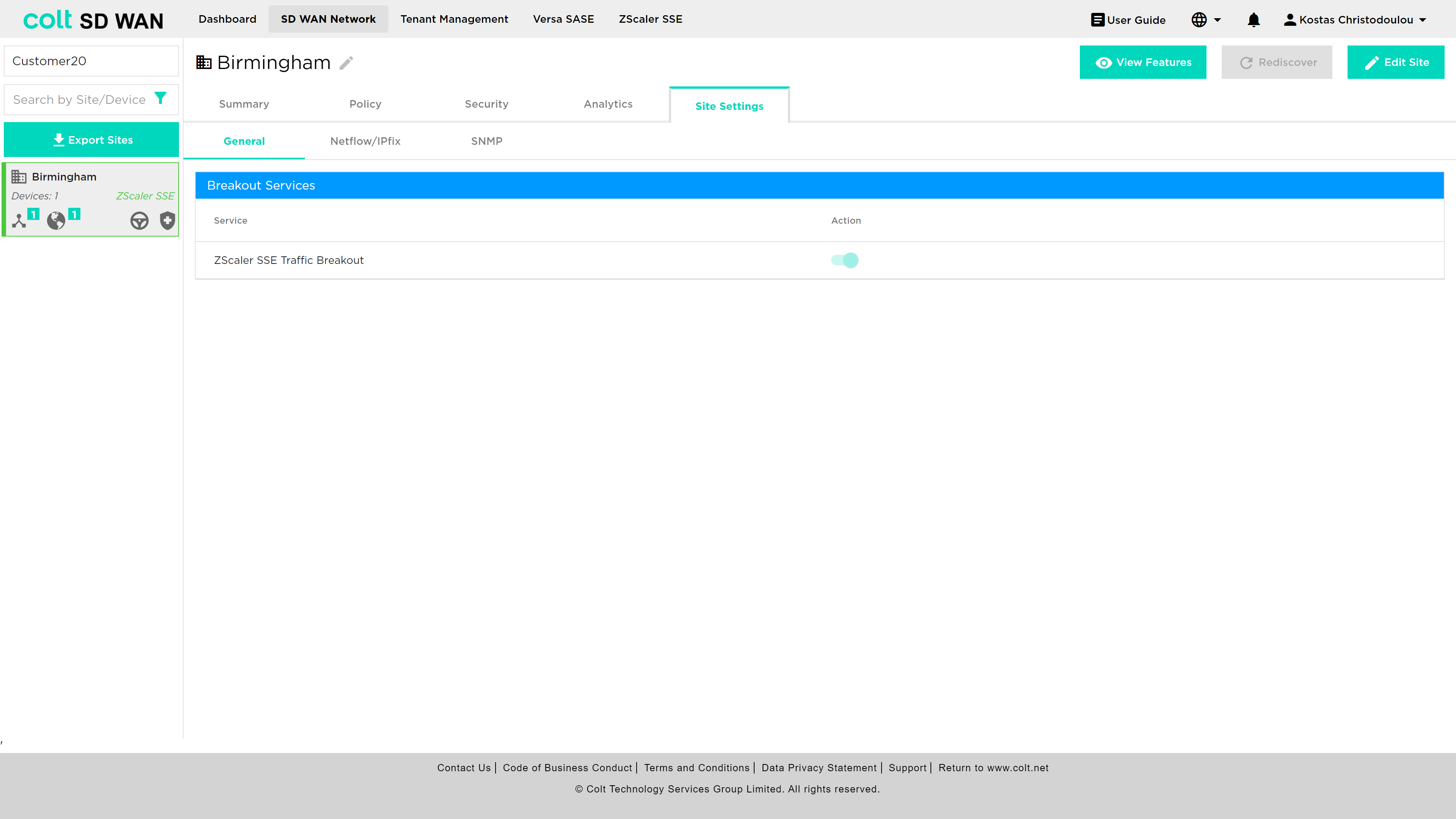
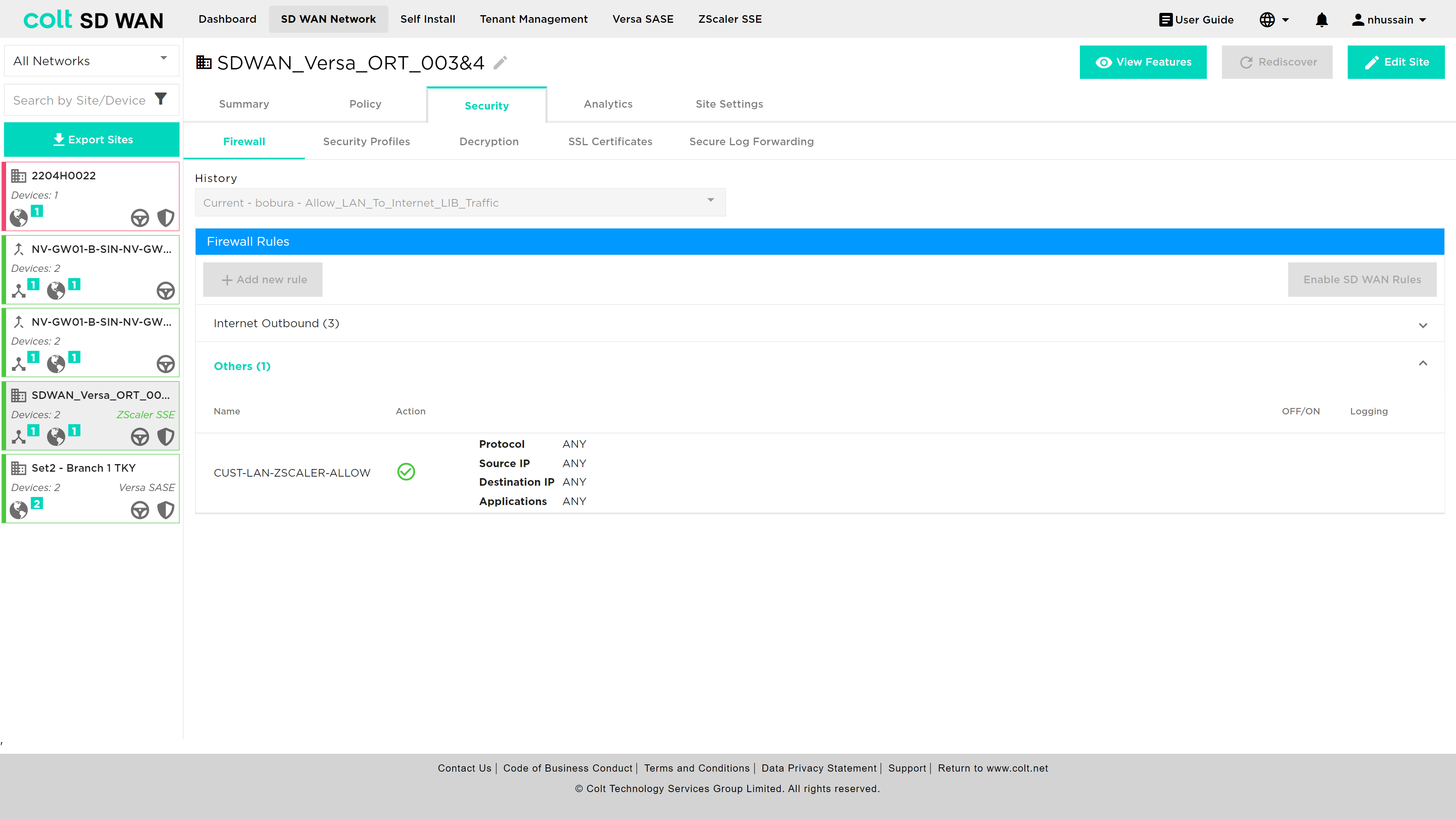
In addition, it’s essential to understand how traffic behaves when LIB or CIB is activated in the context of Zscaler SSE, specifically LIB, CIB and Zscaler SSE: When LIB is enabled for a site along with SSE, traffic by default will always be sent over the preferred SSE GW. In the event that the routes from SSE GW are not available, traffic will be sent over LIB. If CIB is also enabled for customers, there will be an additional backup default route. However, for the traffic to reach the Internet via LIB or CIB, the users need to configure the appropriate firewall and internet traffic steering rules via the SD WAN portal.
Analytics
The Analytics menu option provides a series of submenus that each provide analytics data for the following areas:
-
Interface Analytics (usage of interface, SD WAN and Internet (DIA))
-
Interface QoS Analytics (IP QoS queue usage)
-
Application Analytics (Top application usage or search by application)
-
SLA Metrics (SD WAN path specific SLA measurements)
-
Firewall Analytics (usage by firewall rule)
-
User Analytics (top talker by IP address)
-
Path Analytics (bandwidth consumption per SD WAN path)
There are some common features for the Analytics section:
-
Different metrics can be viewed by selecting the down arrow in the top left corner of each graph
-
Tabular or graphical data can be pinned to the dashboard view using the star icon on the top left corner of chart or table views
-
Data can be downloaded in CSV format files.
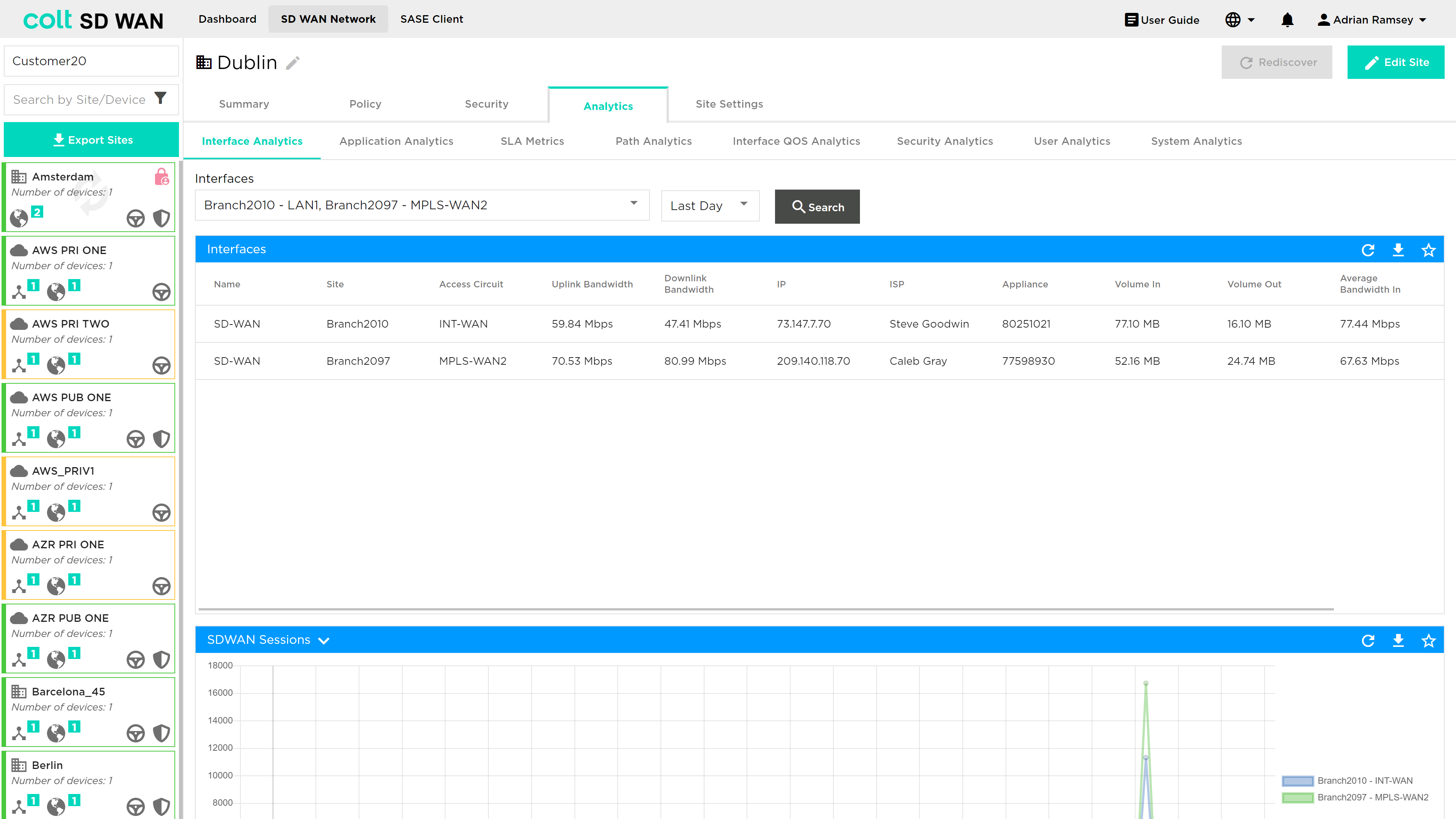
| Analytics data and Log file storage is limited today. The data retention period is 3 months and logs are limited to 10000 per customer per day |
Interface Analytics
Provides a statistical view of the customer’s network via a measurement of networking metrics for SD WAN (aggregate of all SD WAN Paths from that site) traffic and DIA or Internet breakout traffic.
The analytics of each node in that network can be viewed by selecting the ranges in Days, Weeks and Months plus a custom date range. After selecting the date and time ranges, pressing the ‘Refresh’ option will show the section detailing graphs that show the network services for each node being measured against the metrics within the selected timeframes.
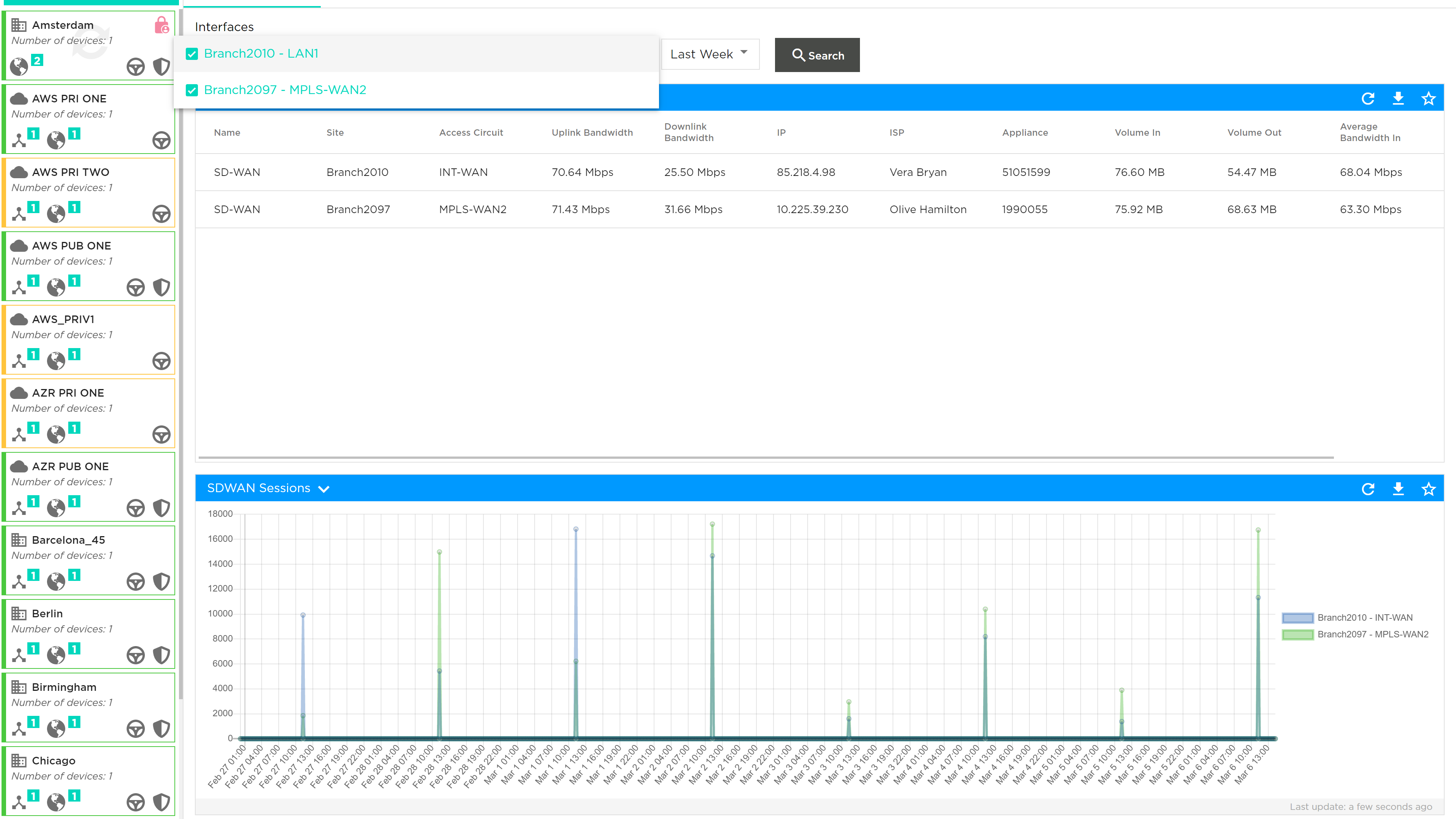
The metrics being measured in this section are:
-
Delay: The amount of time it takes for data to travel across the network from one node to another. It is measured in milliseconds.
-
Jitter in: Random small time interval measured in milliseconds, where messages are cached in the node before being forwarded to avoid traffic collisions while also reducing varying delays to the received packets.
-
Jitter out: The inverse of forward jitter, where the amount of varying delays increases due to messages being forwarded and colliding with existing network traffic
-
Packet loss in: The ratio of forward loss divided by forward transmit count measured in percentage
-
Packet loss out: The ratio of reverse loss divided by reverse transmit count measured in percentage
The metric to be viewed can be selected by clicking on the down arrow at the top left corner of each graph.
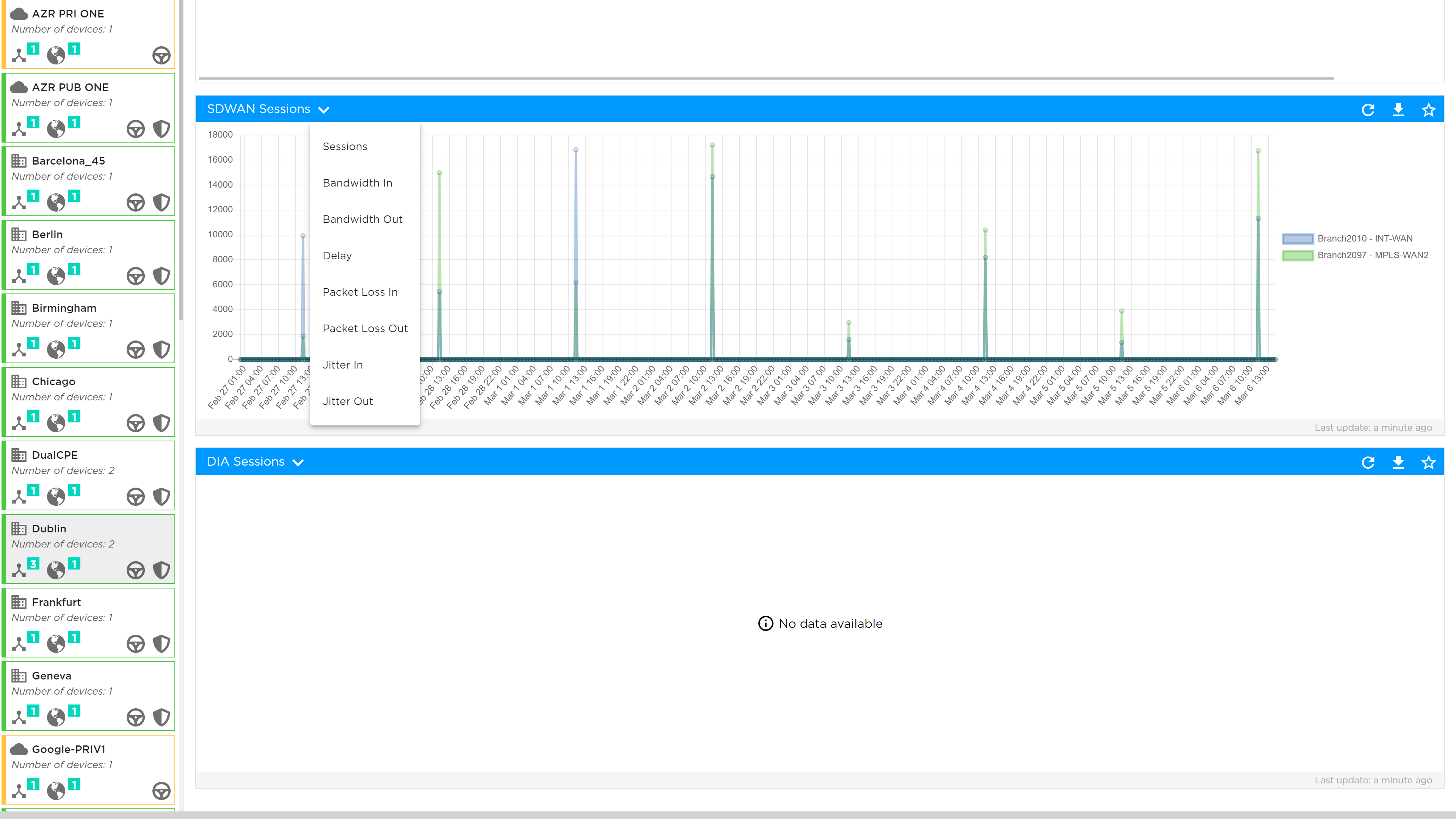
| The lowest level of granularity is a 5 minute average for reports up to 24 hours. The “averaged data period” displayed changes when the reporting period is longer. |
Hovering the mouse cursor over the graph lines shows the exact value of these metrics; while the user can zoom in and out of these charts to expand and reduce the date range to view the data trend of the analytics more clearly.
Application Analytics
In this section you can see the performance of your applications. Select the interface, the number of applications you want to be shown and the time period you are interested in. In addition you can search and report on specific applications:
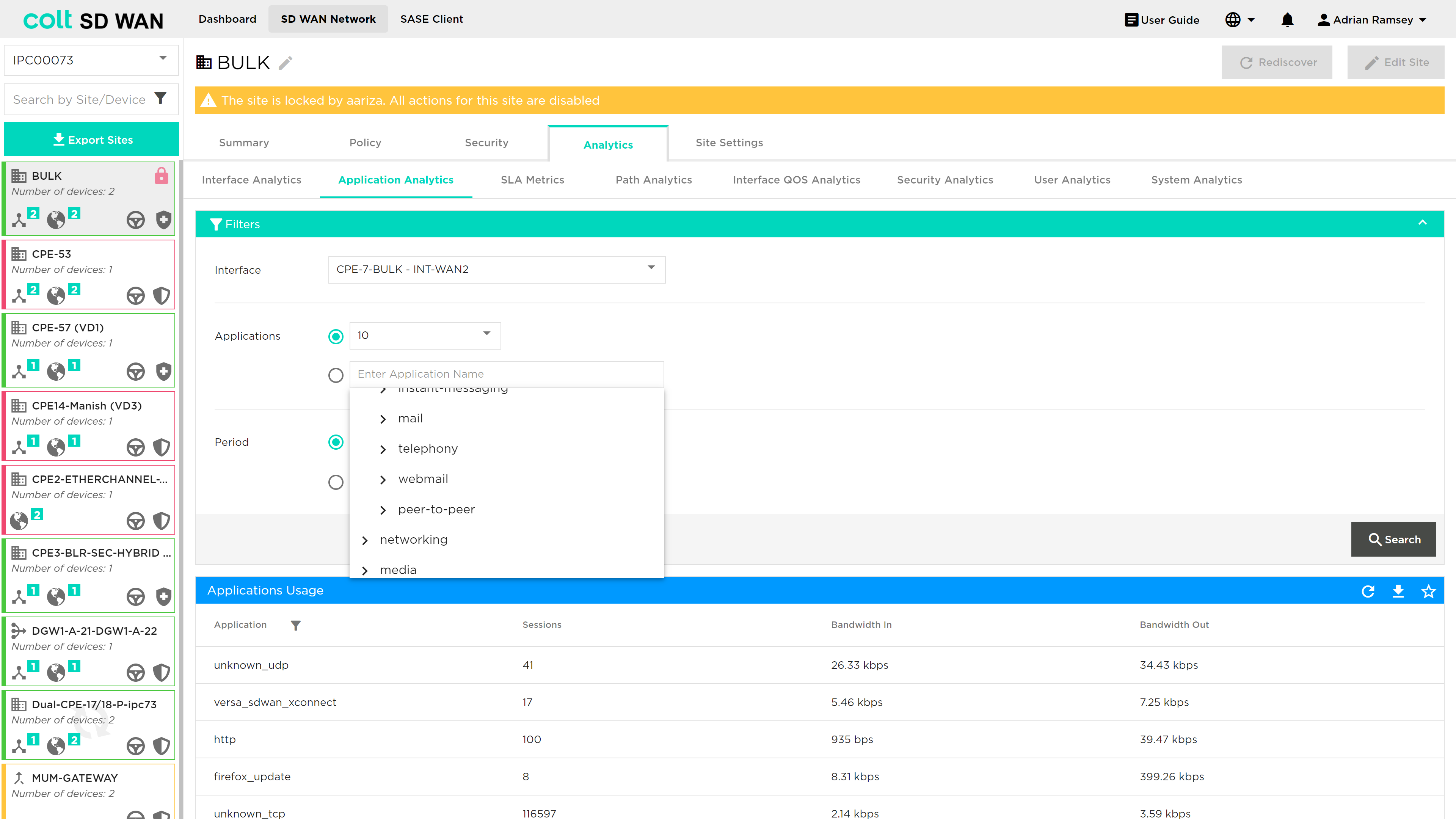
The data will be displayed in selected timeframe showing the following metrics which can be viewed graphically or in a tabular format:
-
Bandwidth In
-
Bandwidth Out
-
Sessions
-
Bandwidth
In addition reports can be downloaded in CSV format or pinned to the dashboard view.

Firewall Analytics
Portal users will be able to view usage metrics of most frequently hit firewall rules as shown below. The view can be changed by data and depth of most frequently used rules.
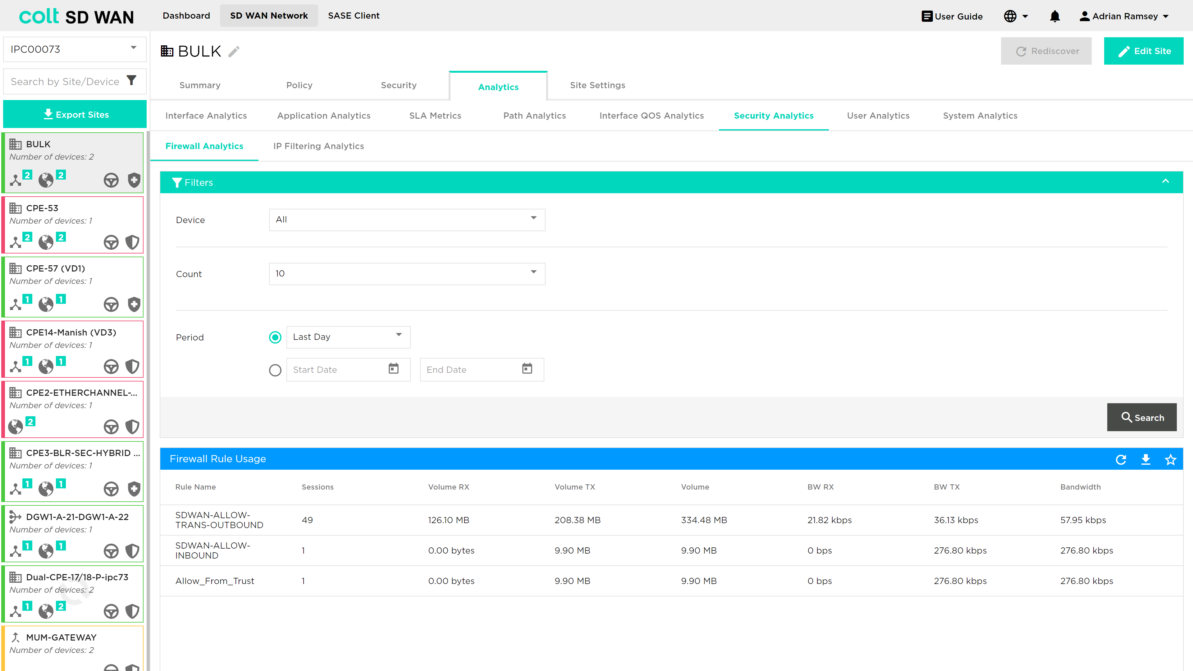
Graphical and tabular view of the data showing usage by: session, Bandwidth, Volume in both Transmit and Receive directions are available.
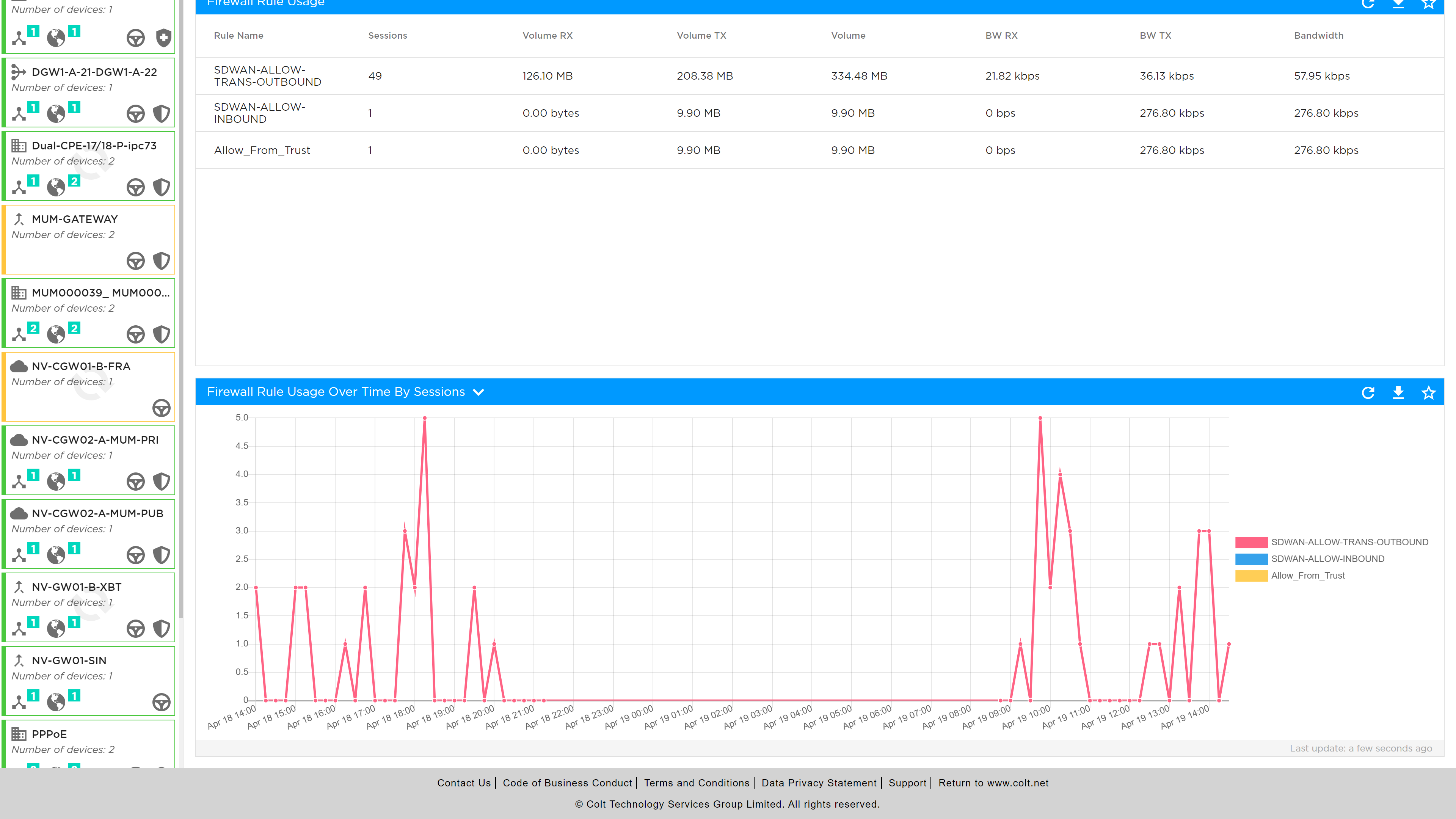
The Firewall Logfiles can be viewed and downloaded as a tabular format or downloaded as a CSV file.
Log files include date/timestamp, IP address, protocol, action, device and type i.e. session start or end logging
Interface QoS Analytics
The interface QoS analytics shows usage by COS, please note that not all CoS or DSCP values are shown separately, but some are grouped as follows:
-
Best Effort: includes Best effort, Assured and Default CoS
-
Network Class of Service
-
Expedited Forwarding
As with all other metrics this data can be viewed per interface, with standard and custom time ranges.
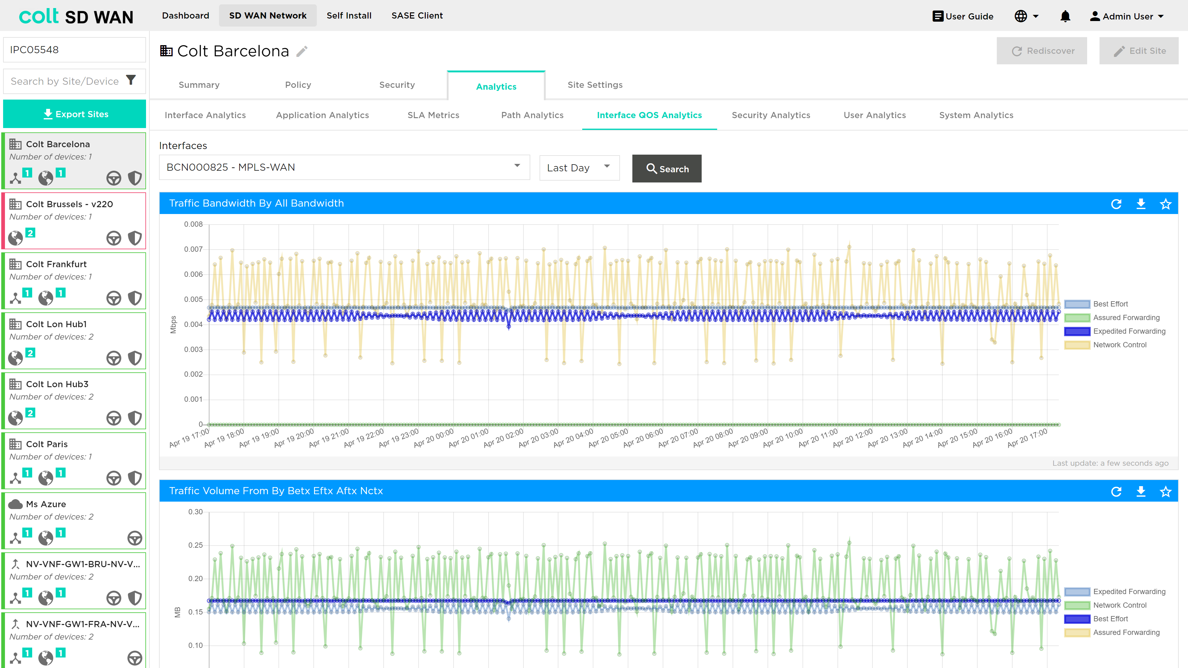
Usage data on the by these forwarding classes are shown in graphical form
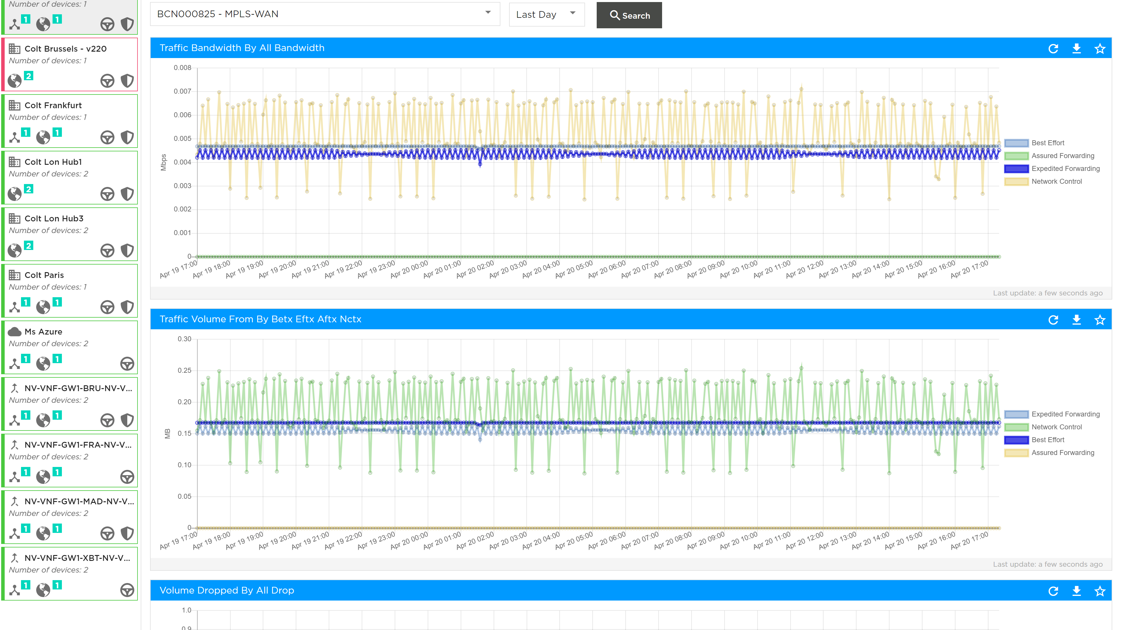
The packet drop per drop profile associated with forwarding class egress profile can be viewed as shown below.
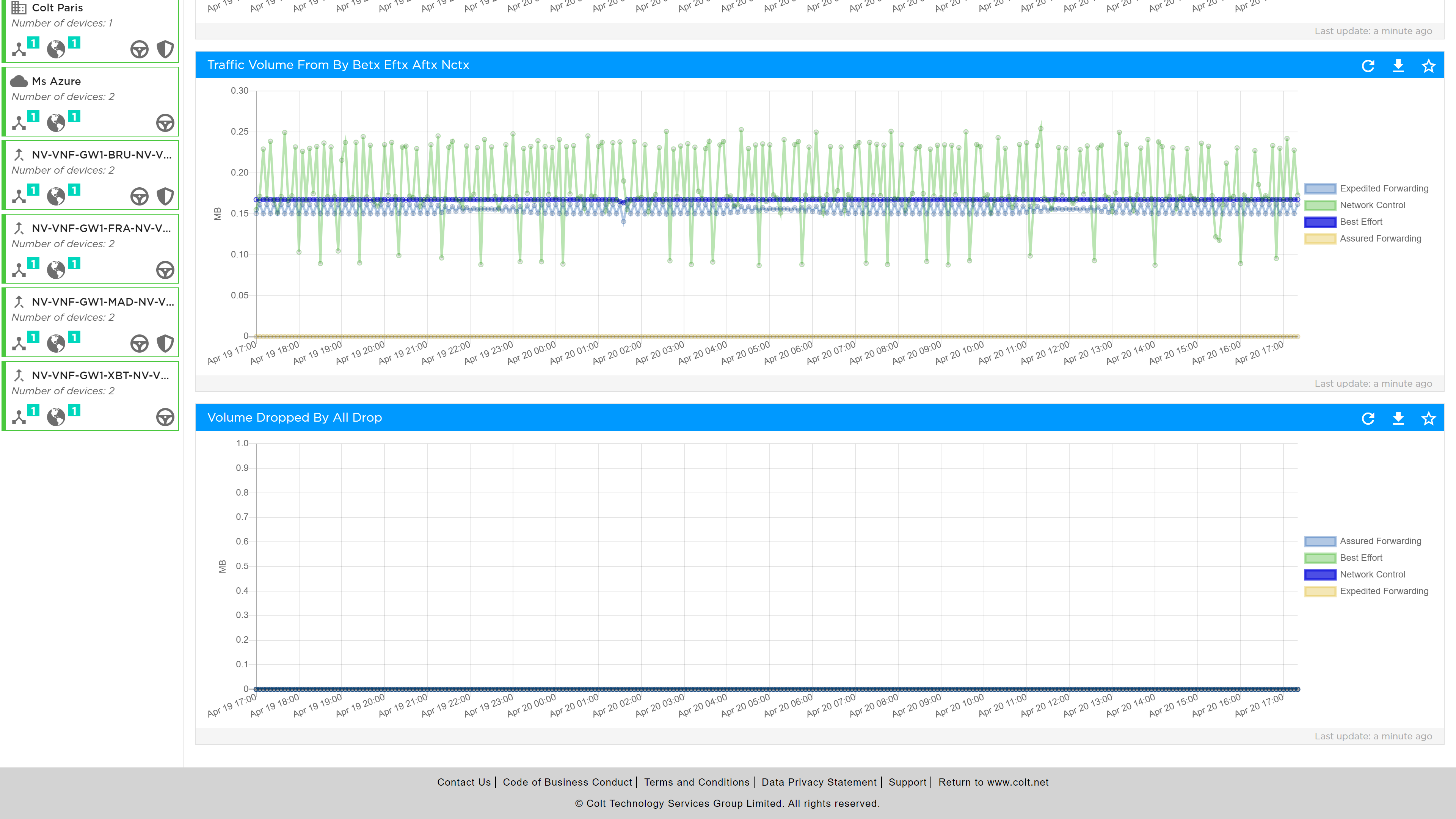
SLA Metrics
The SLA Metrics analytics provide a view of the specific SLA values per path, where a path can be between the site and one or all the termination CPE. This is selectable as follows:
-
By remote device
-
By Interface
-
By Group of top used paths
-
Predefined periods: day, week or month
-
Custom date range
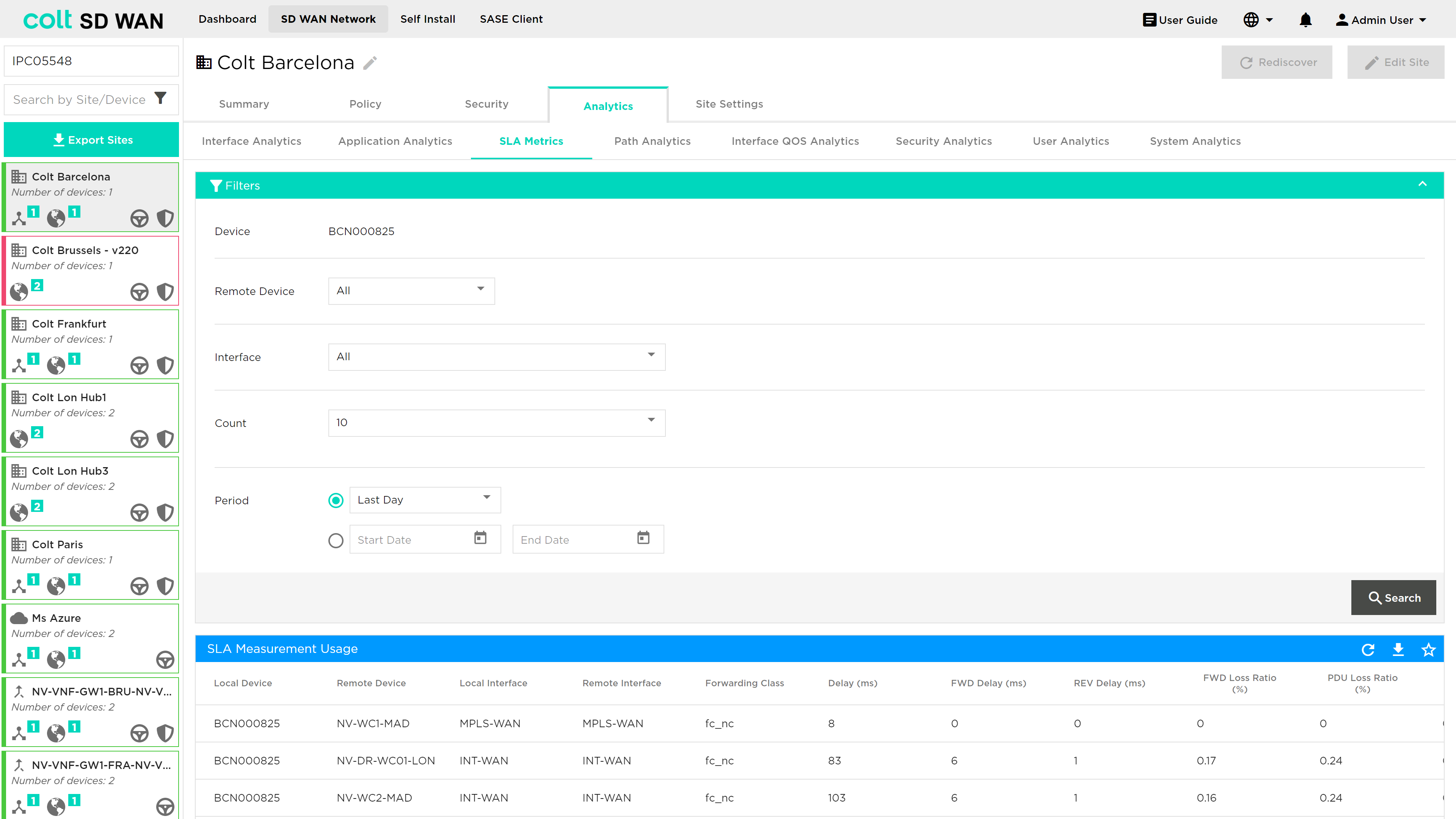
SLA metrics can be viewed are as follows:
-
Delay: Maximum link latency
-
Jitter: Forward and reverse delay variation
-
Packet loss percentage: Total percentage of forward and reverse packet loss in a flow
-
Forward loss: Packet loss in the forward direction
-
Reverse loss: Packet loss in the reverse direction
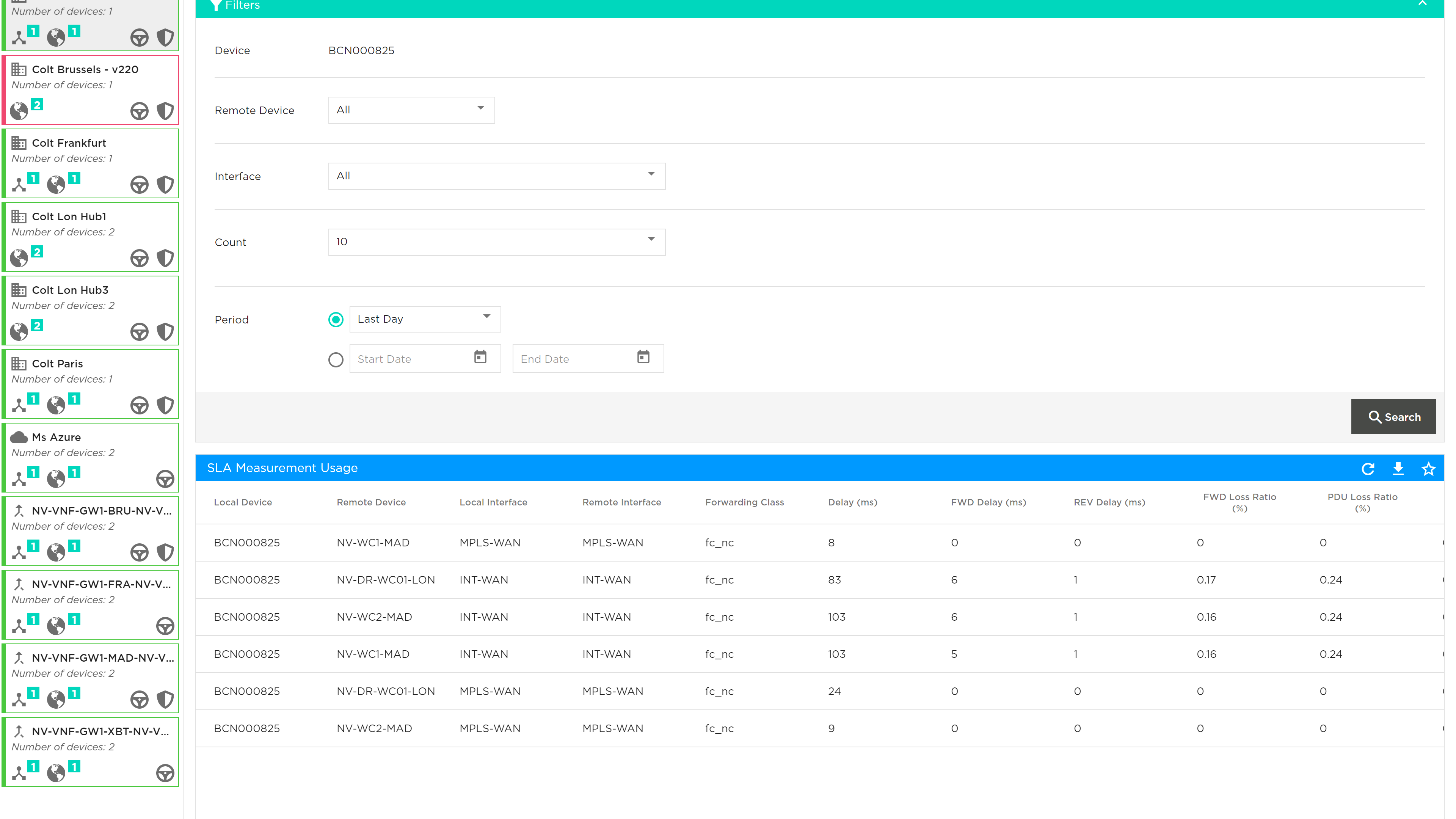
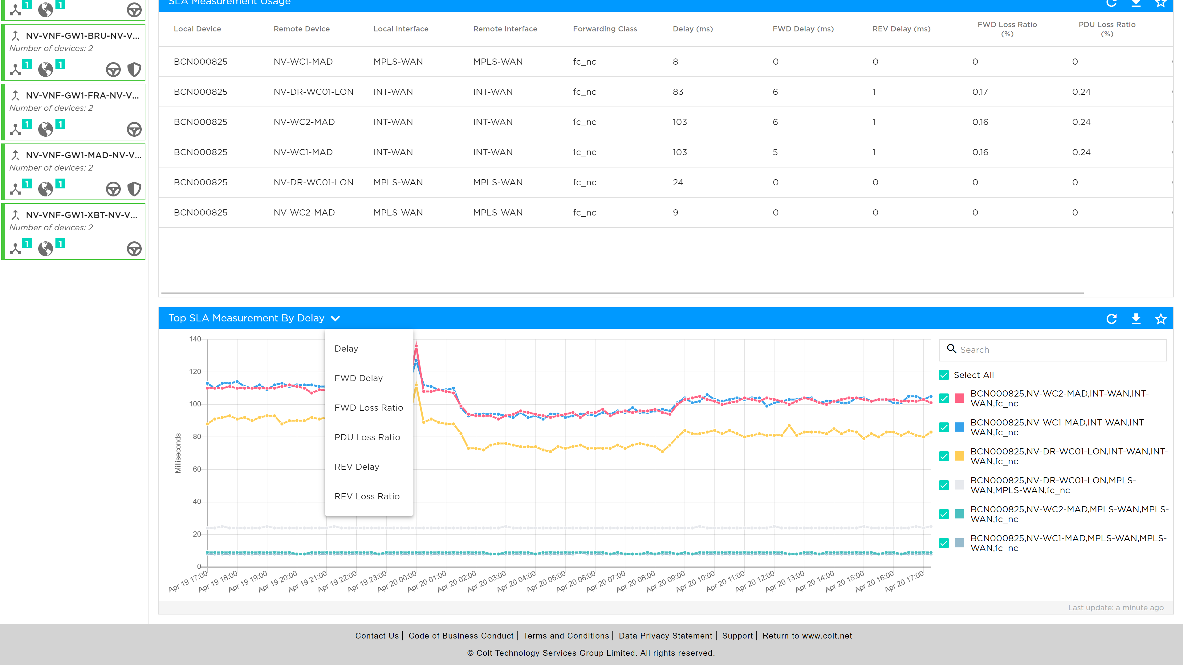
User Analytics
The user analytics provide usage date IP addresses on the LAN or DMZ which are consuming the WAN bandwidth. Reports can be generated by:
-
WAN Interface
-
Depth or number of top users
-
Predefined date
-
Custom date ranges
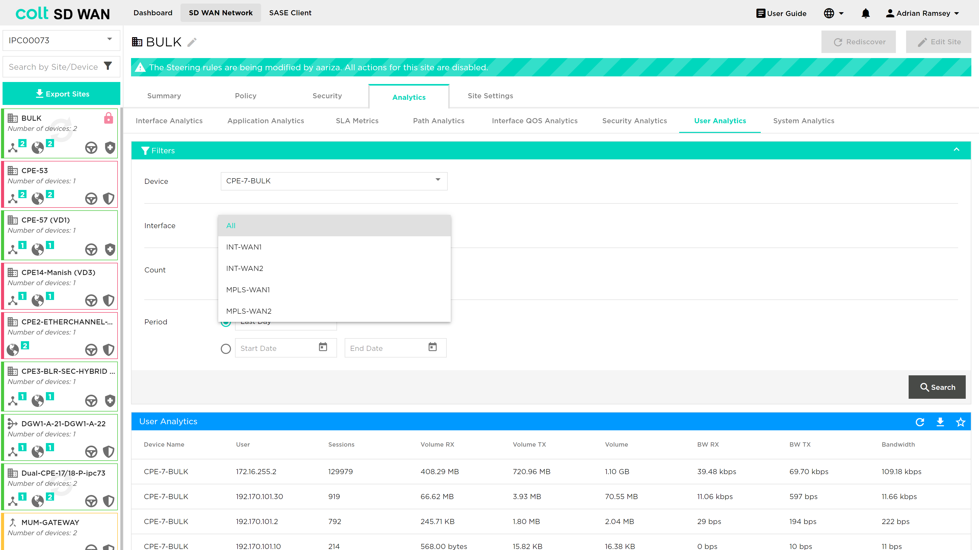
The reports can be shown as tabular or graphical views by source IP address in the following metrics: sessions, average session duration, data volume, Volume and Bandwidth by total or in the transmit/receive directions.
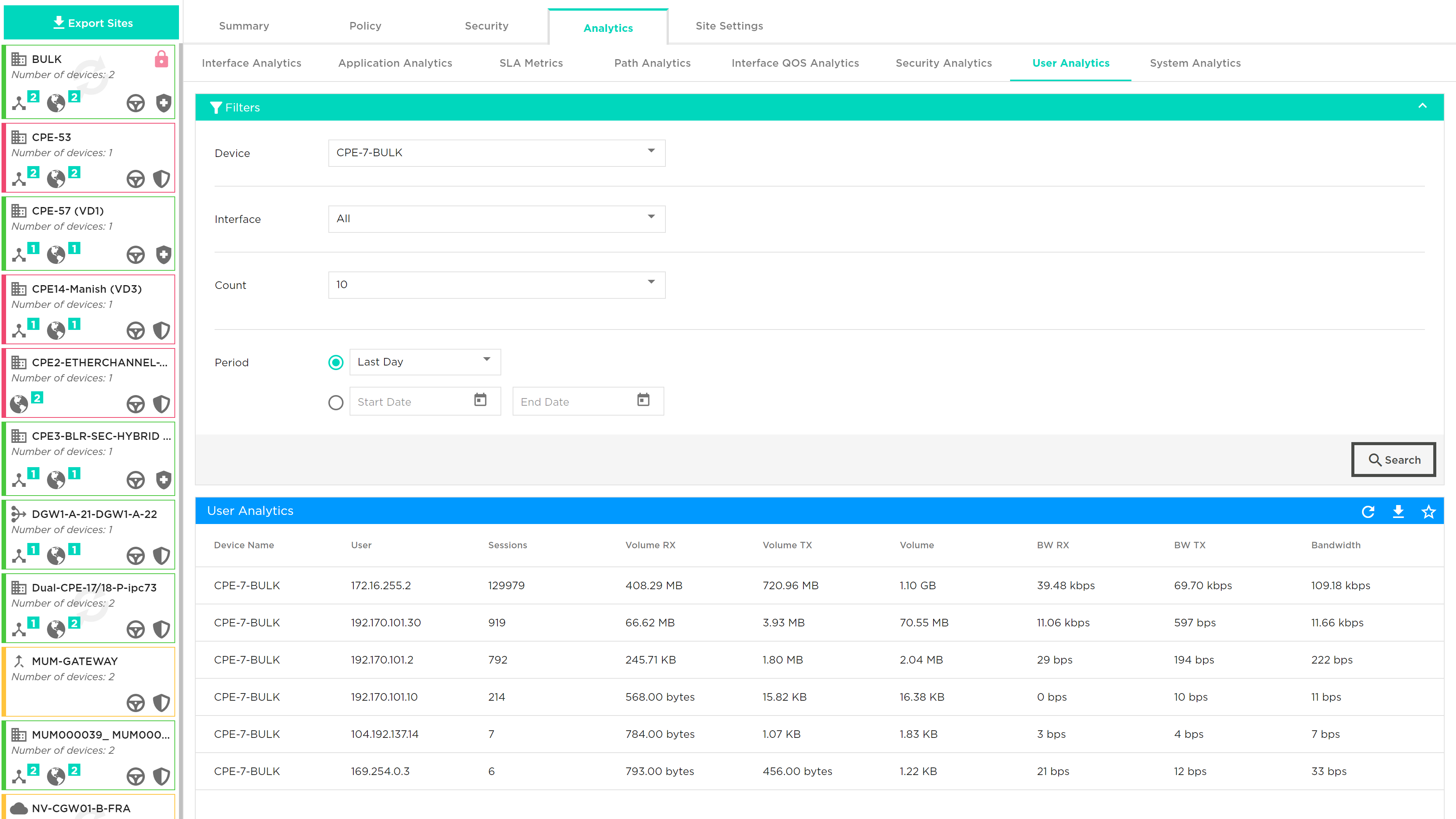
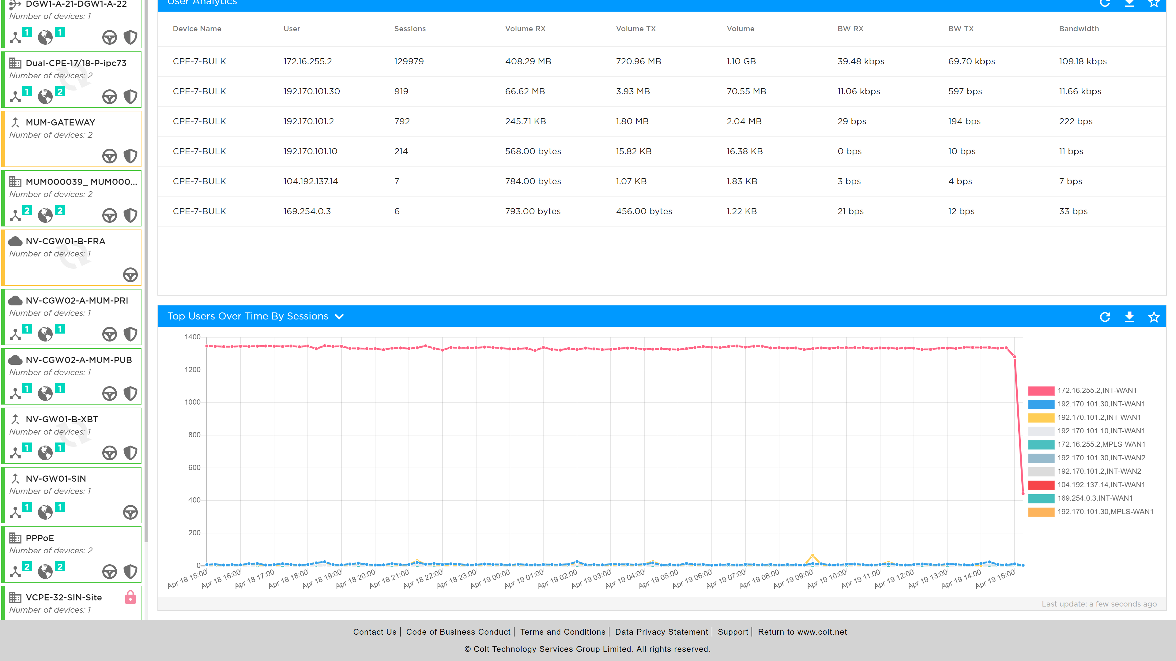
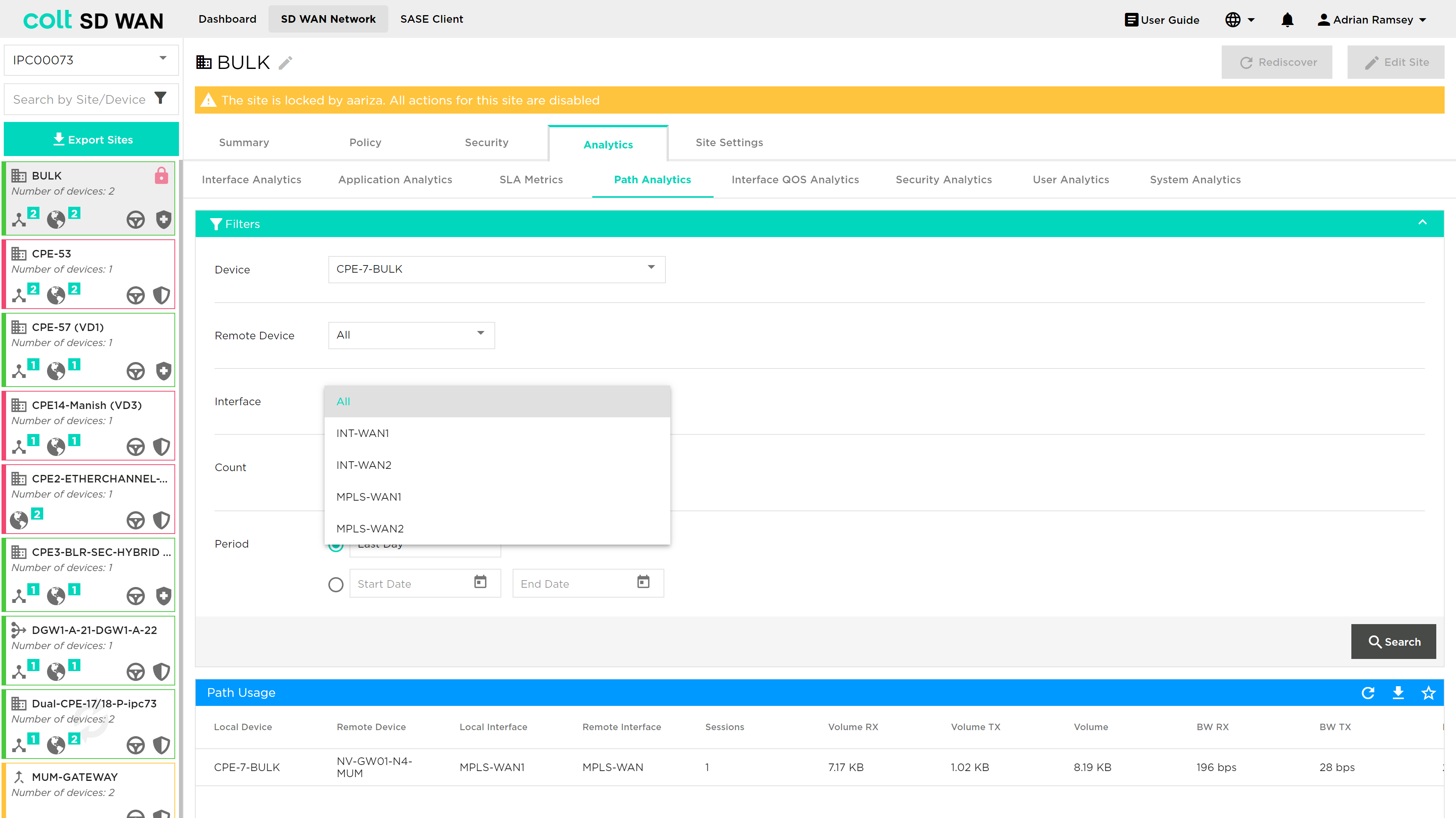
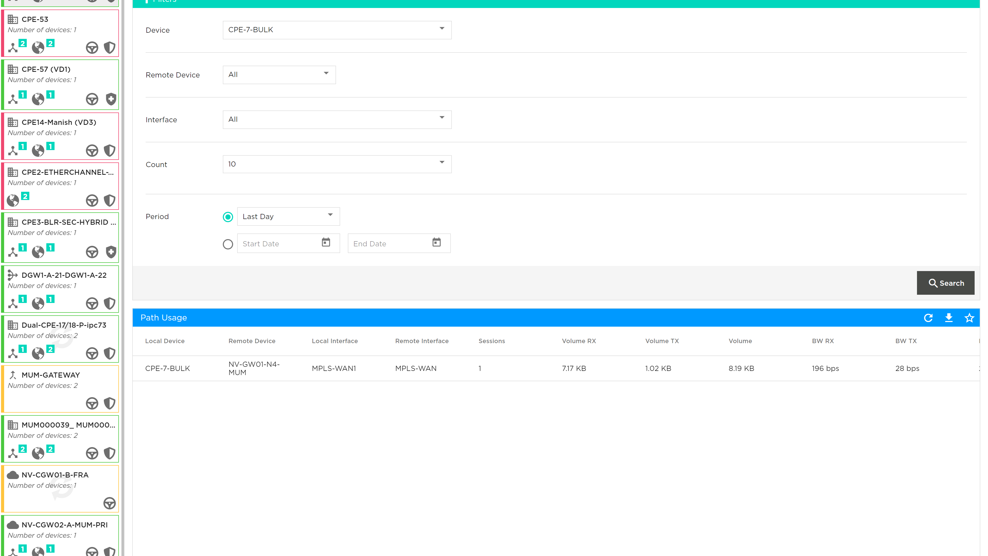
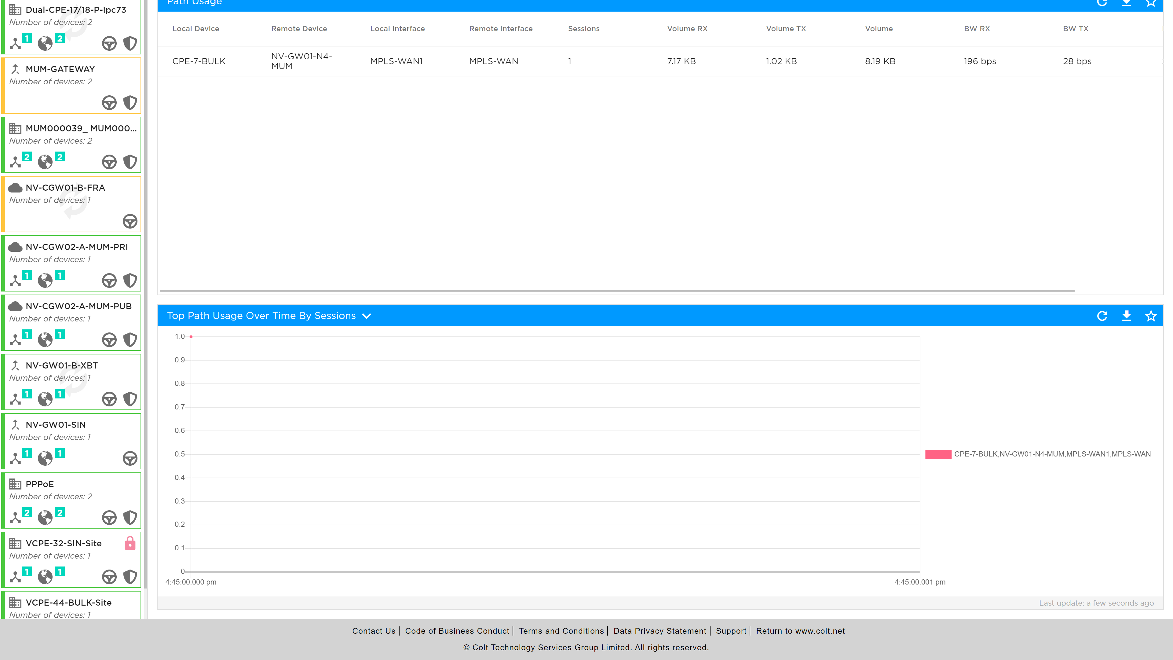
Objects
It simplifies policy management by allowing named address objects and groups to be used in place of individual IP addresses, making policies more readable and easier to manage. Customers can create address objects and group multiple addresses into a single address group, streamlining policy application and reducing complexity. It is also possible to create custom service objects based on protocol, port range, and source/destination ports that will provide enhanced control over the traffic allowed or denied by security policies.
Address objects and groups also improve network identification by enabling specific IPs or subnets to be identified with descriptive names, making the system more intuitive and manageable.
These objects can now be created at the site level and associated with multiple rules—a significant improvement over our previous way, where each rule required a separate object. This change allows customers to make updates at the object level, automatically reflecting changes across all associated rules, eliminating the need to manually update each rule individually. This feature leads to greater efficiency, as address objects and groups reduce the number of entries in policies, speeding up configuration and minimizing errors.
How to configure:
In the SD WAN Summary page, go to the Objects > User Defined
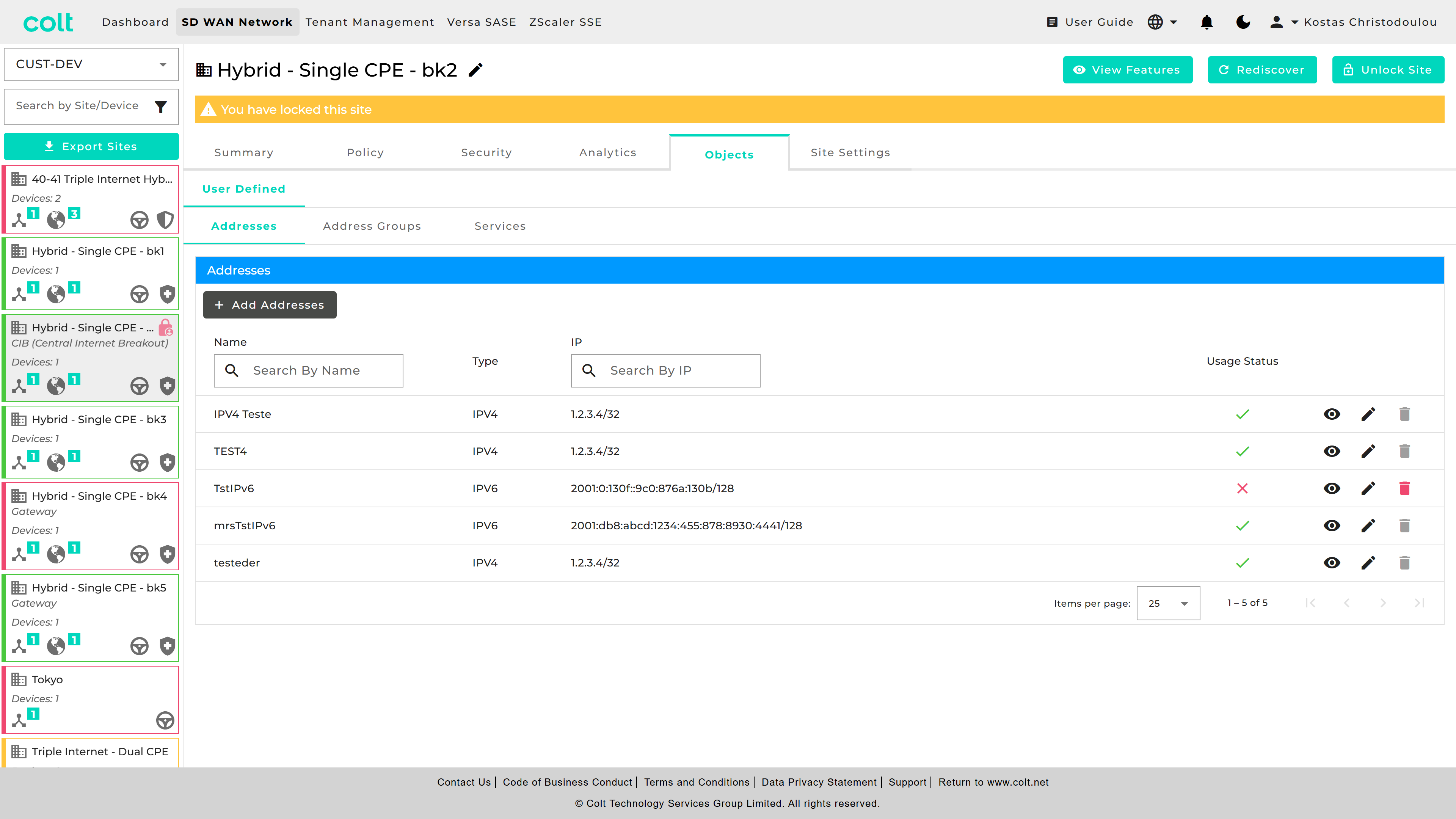
| You can check the "Usage Status" and eye icon, to understand if your object is currently being used in other objects/groups or for any Traffic/Firewall rules. |
If you want to do a single Address Object, go to “Addresses” and press “+Add Addresses”. Then fill the necessary fields out.
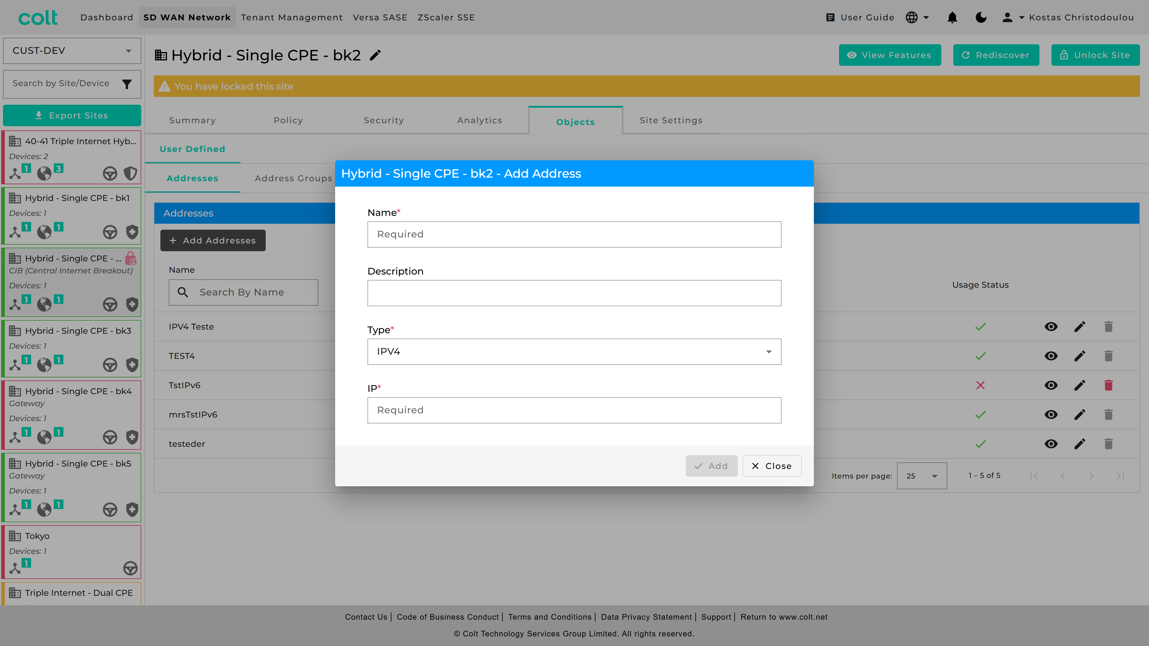
For Address Groups, got to respective tab and press “+Add Address Group” and fill out the fields.
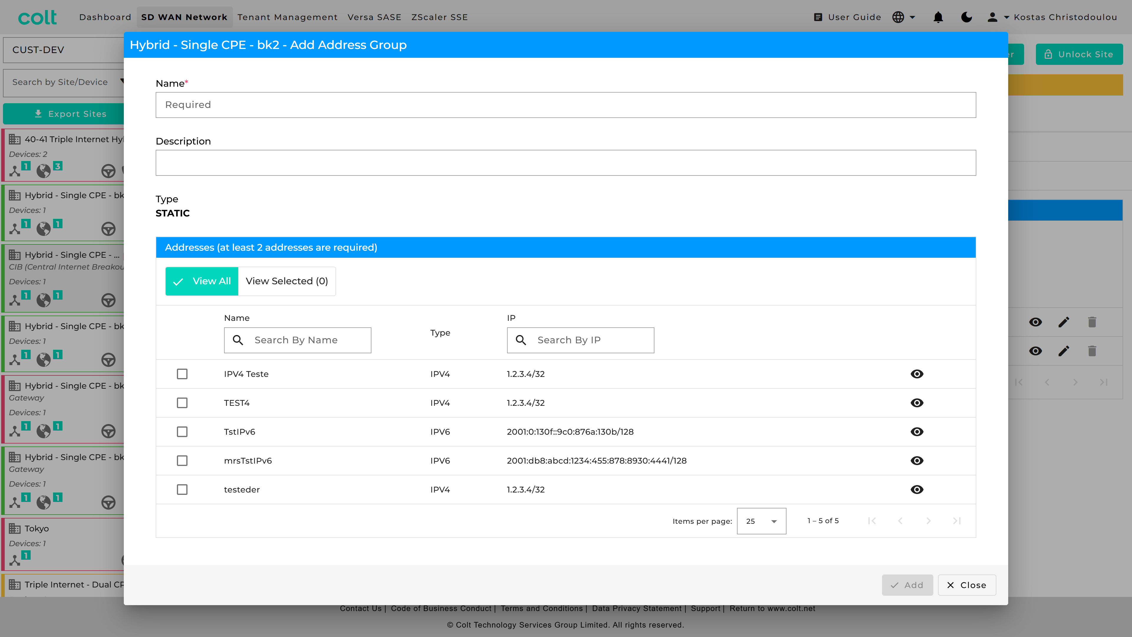
For port groups, got to “Services” and press “+Add Service”.
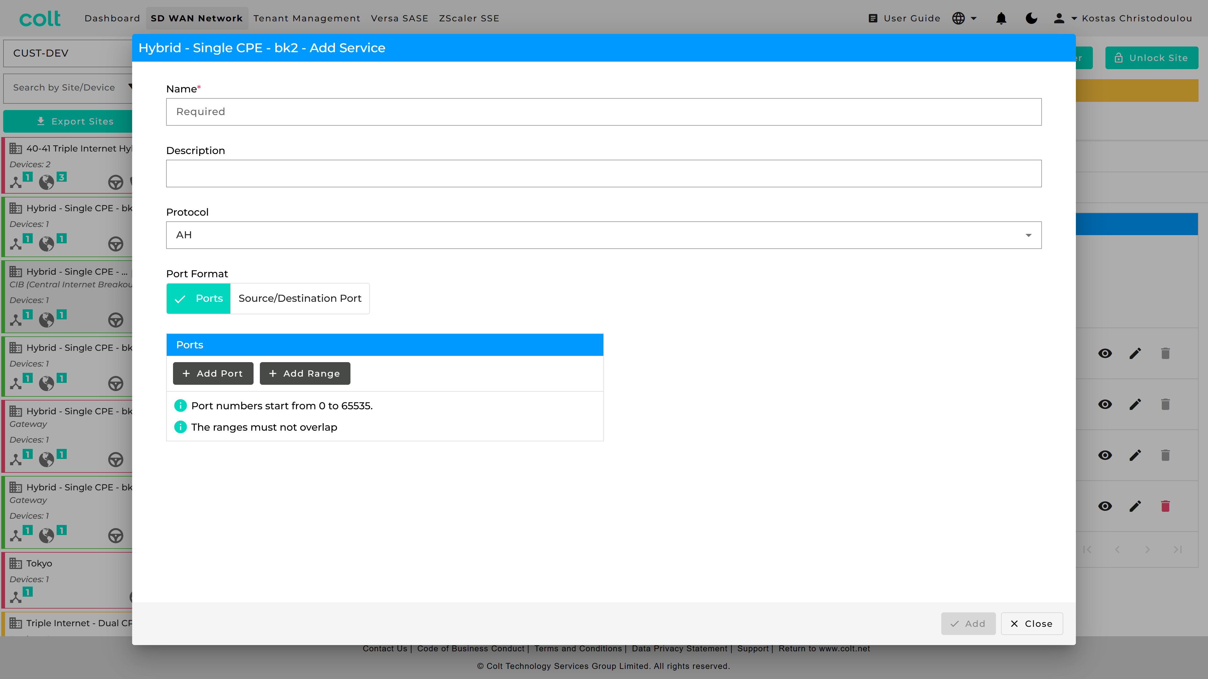
In order to put what you created in use, you can find them in Traffic Steering Rules, Firewall Rules, Decryption and DDoS. As an example see how it looks below in the “Firewall” tab.
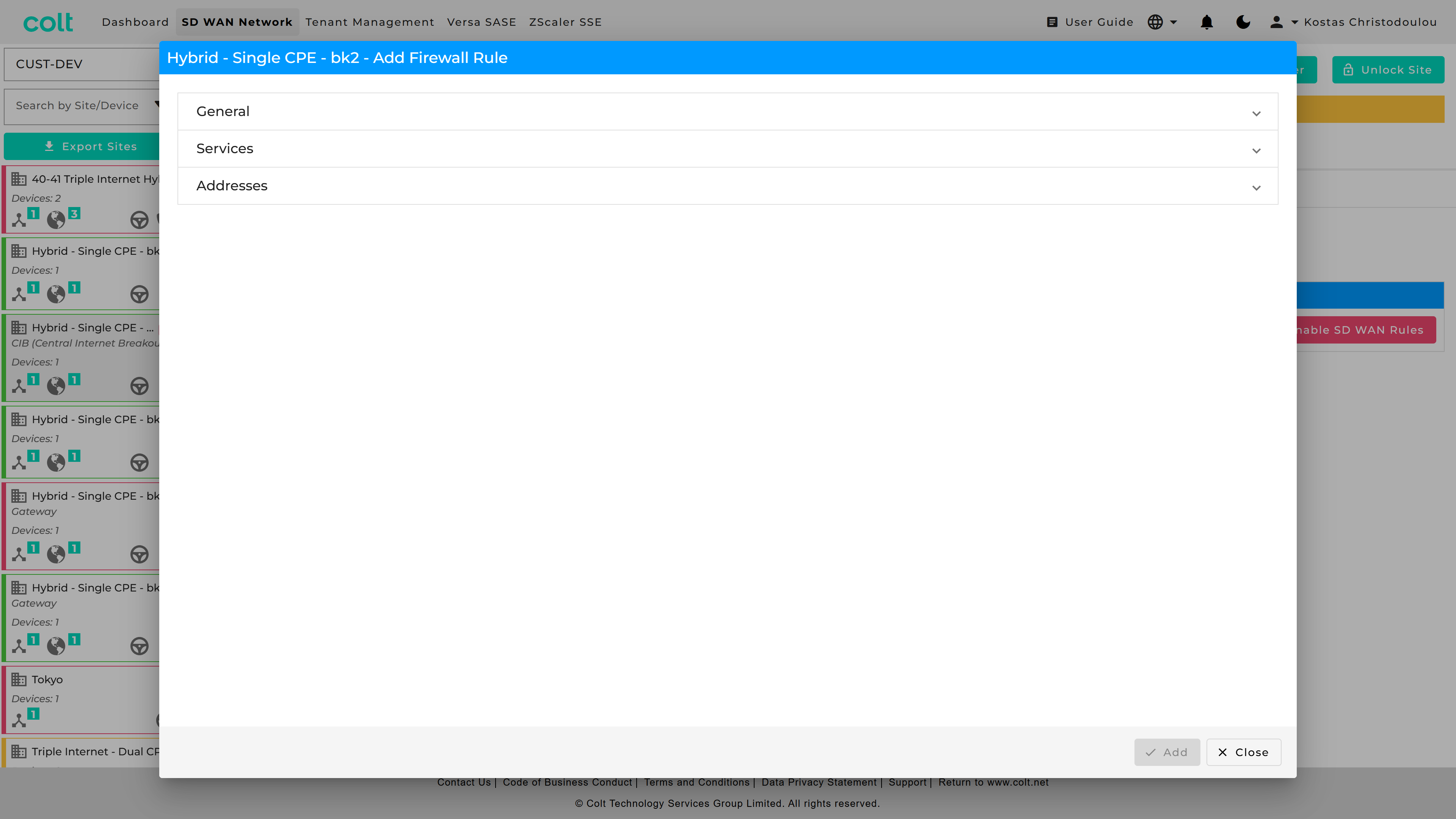
You can see the new “accordion” look. If you go in “Services” you can check “Port” to use the old way, or “Object” for the new way and get a list of the objects you have created.
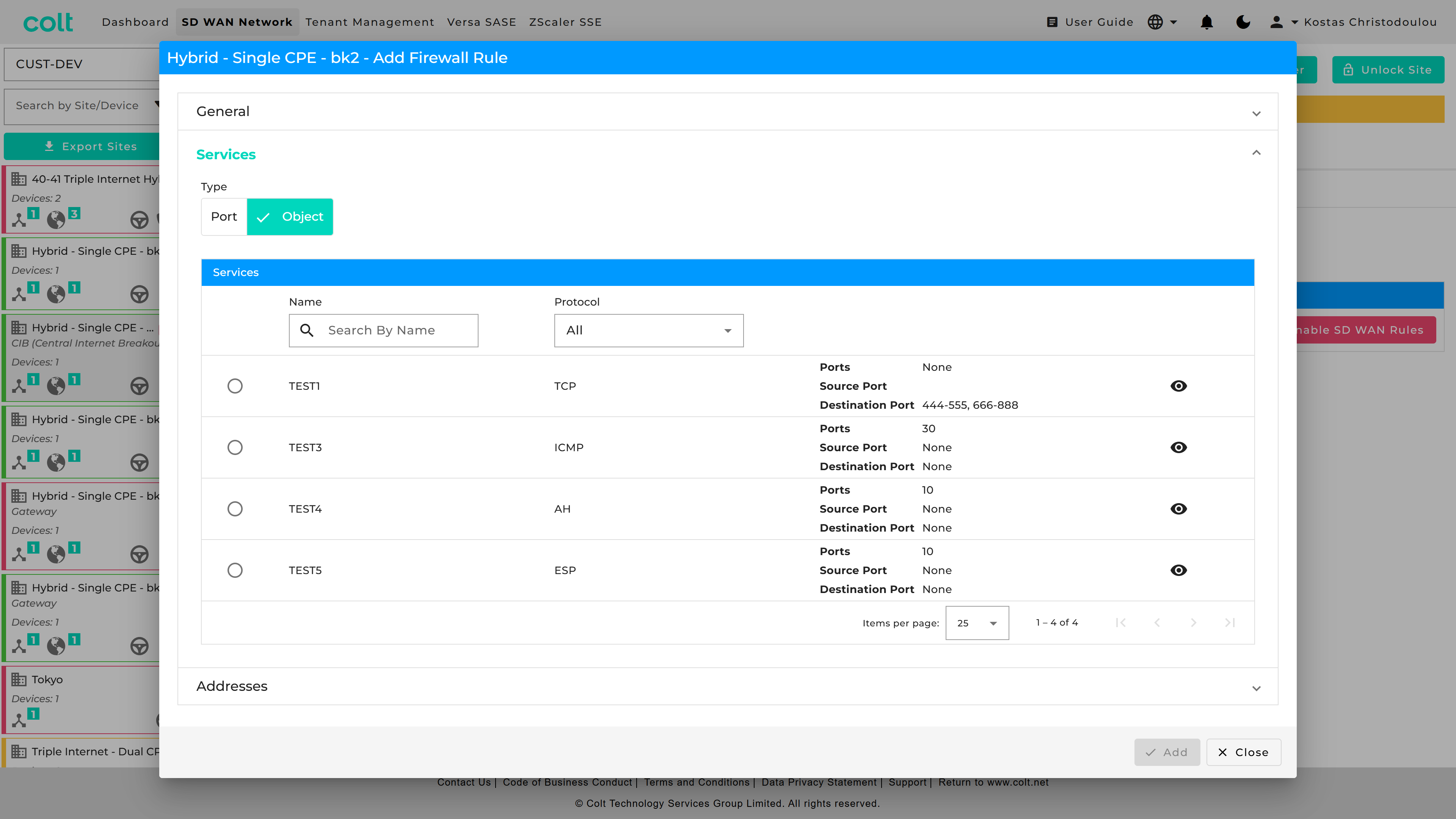
Similarly, you can do for Addresses.
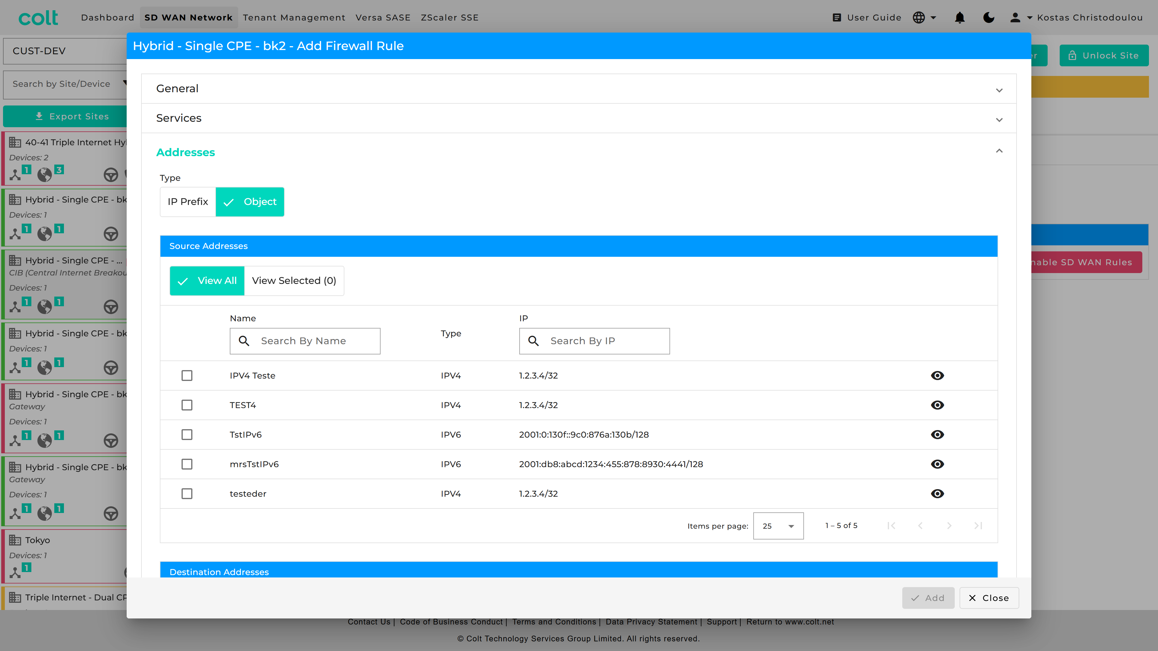
User Defined Categories
The Portal allows users to create, manage custom URL Categories as Objects or view existing Predefined Categories. User Defined URL Categories can be associated with URL Filtering profiles, and have decryption bypass rules configured based on them.
Users can define custom URL Categories by specifying patterns or strings, assigning a Trustworthy reputation by default, and incorporating them into URL Filtering profiles. Users can also define decryption policy rules with No Decrypt action.
String is a specific URL and pattern is a template that can match multiple URLs with similar structures.
-
Example URL string: www.facebook.com.
-
Regex pattern examples:
-
".*facebook.*" (.*<string>.*)
-
"(\w*\.)twitter.com(\/.*)"
-
| The portal supports standard regex patterns. It is recommended to define strict pattern matches; otherwise, similar URLs may unintentionally match the defined patterns. To test your regex pattern, you can use public tools such as regexr.com or regextester.com to validate whether the URL string matches the intended regex pattern. |
Below you can see where to create and configure User Defined URL Categories,
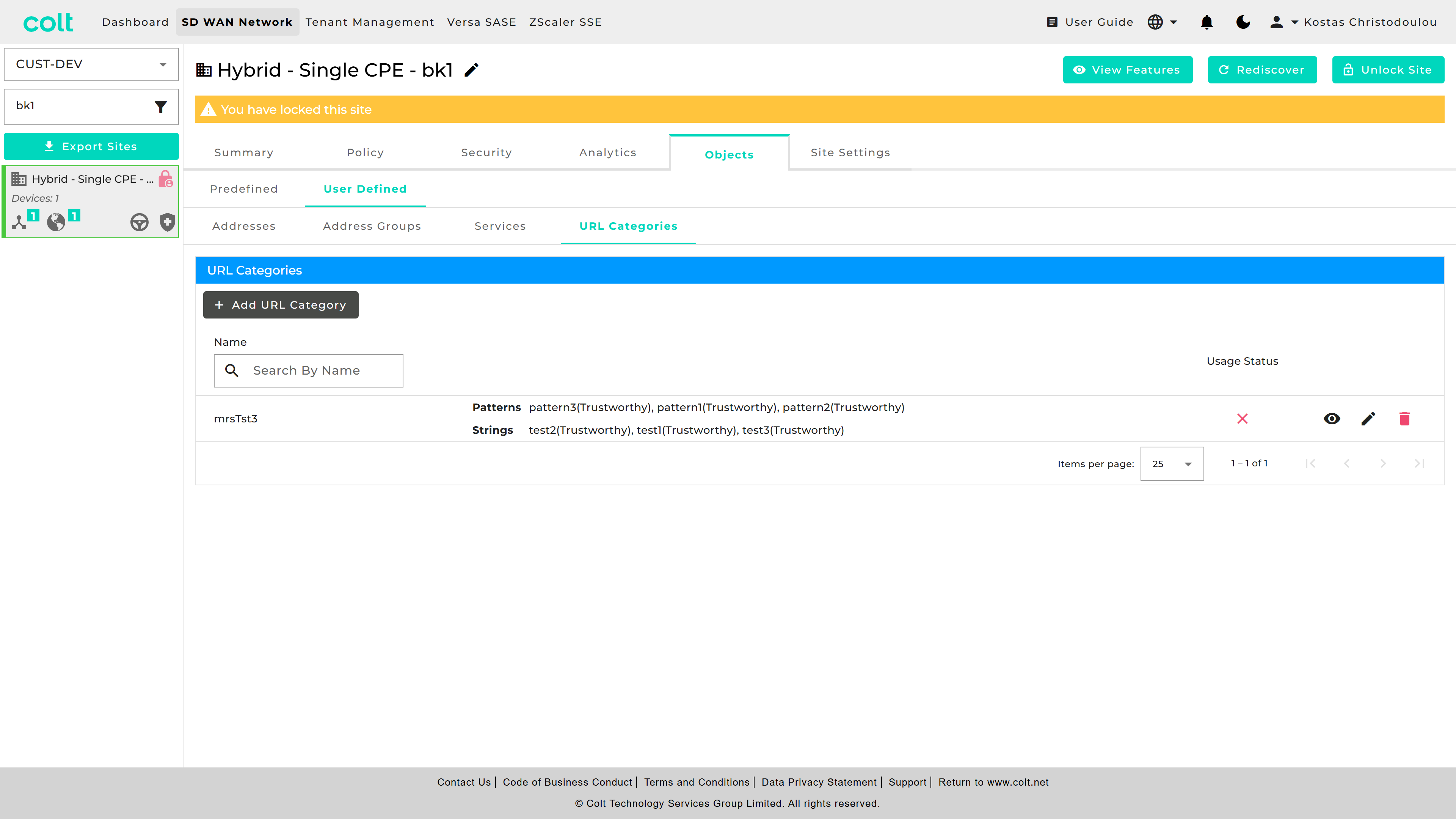
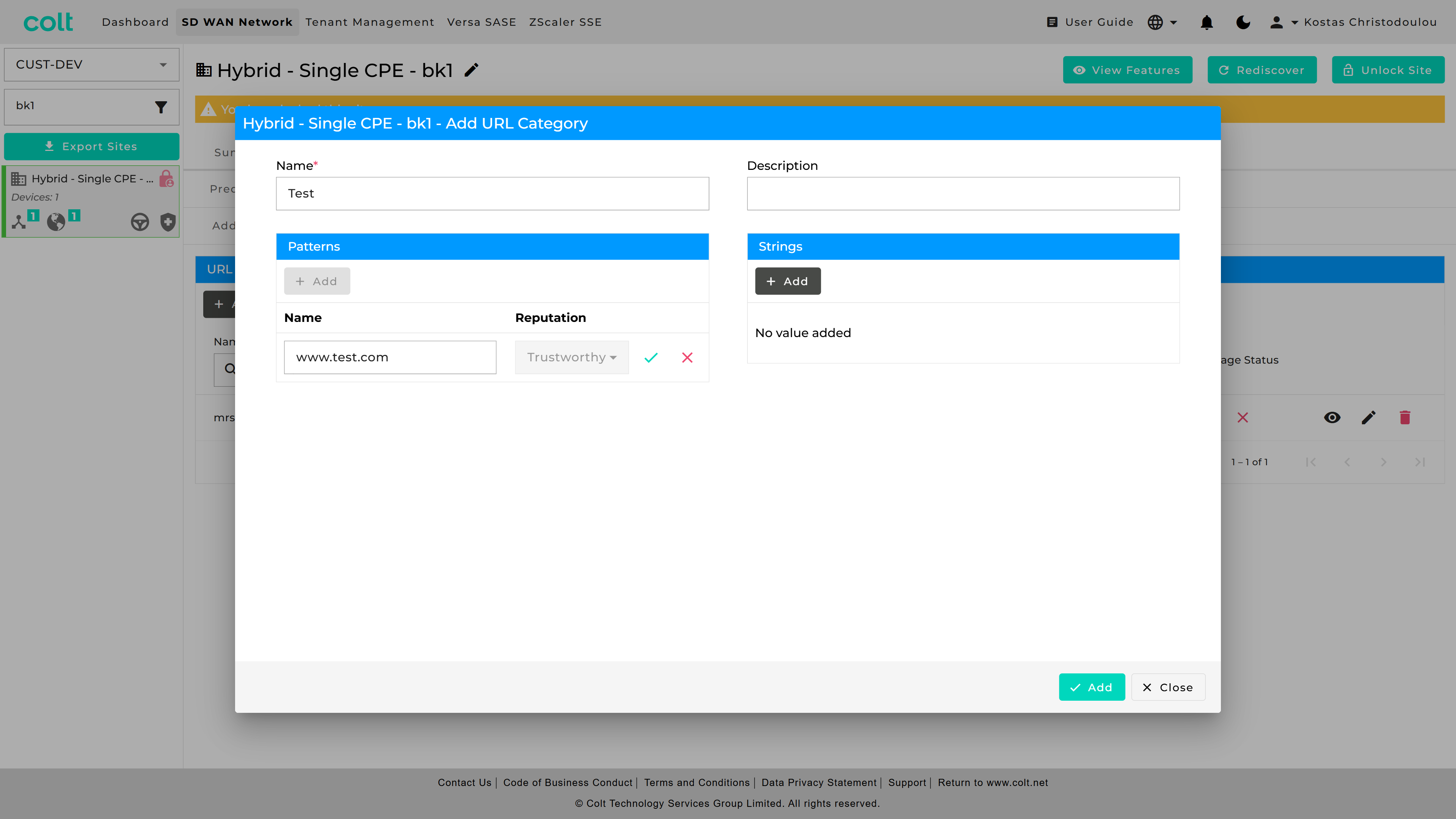
and where to check the list of available Predefined URL Categories.
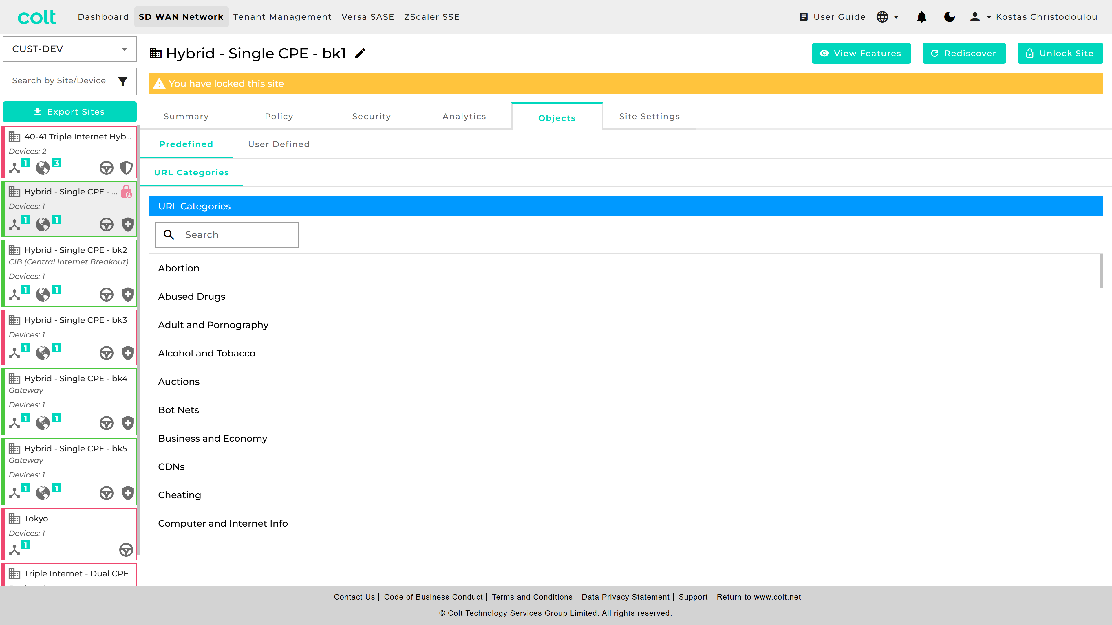
The created Custom URL Categories appear in the User Defined category list for URL filtering with possible actions of Allow and Alert.
Additionally, customers can configure decryption rules to exclude specific URL Categories from decryption, ensuring seamless traffic handling. These rules have to be always set to No-Decrypt and take precedence in rule order. This feature is available when the Network Destination is towards the Internet. The new functionality enhances flexibility while maintaining existing security and network policies.
Site Settings
The Site Settings tab provides three submenus that each cover a different topic:
-
General Settings
-
Netflow/IPfix
-
SNMP
General Settings
This newly introduced tab is designed to host future developments that are site affecting. For the moment it hosts the activation/deactivation button for Versa SASE and Zscaler SSE (if contracted) and allows for the option to rename VRF interfaces in a personalised way with an alias that makes them easy to recognise. The alias change is then visible in the Summary page.
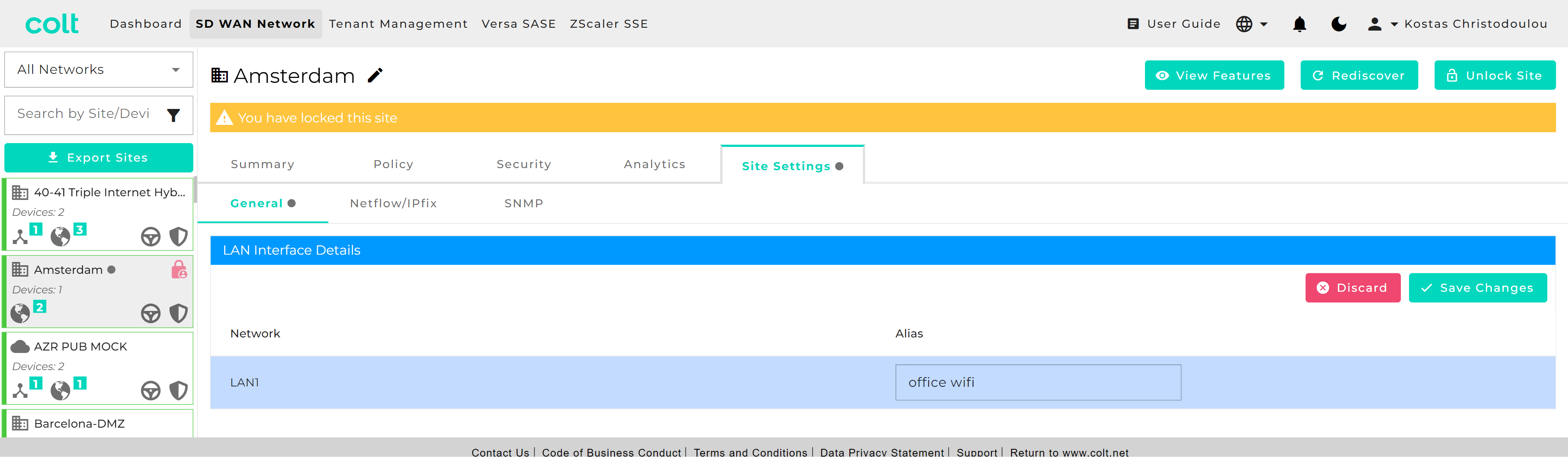
Netflow/IPFix
This features provides the ability to provision an IP address for a TCP/UDP connection for a flow log collector. The service allows Netflow log files using the IPFix protocol to be transferred to a type approved server that can be hosted on an the Colt SD WAN or any reachable IP network.
Note that if a customer’s NetFlow server requires SNMP Read Only access to the CPE, then SNMP Read Only access must be enabled using the SD WAN portal for the respective NetFlow collector. Please see section 16.
The Netflow/IPfix configuration is a site level main menu option as shown below. Multiple TCP log collectors can be created per site or VPN up to a maximum of 4, but only one UDP collector. The order of precedence is based on the order the rules are created.
| When configuring collectors for Secure Log Forwarding (SLF) and NetFlow on the same server, please make sure that the combination of Destination Address and Destination Port is unique for each collector. This means you cannot use the same IP address and port combination for both SLF and NetFlow collectors. |
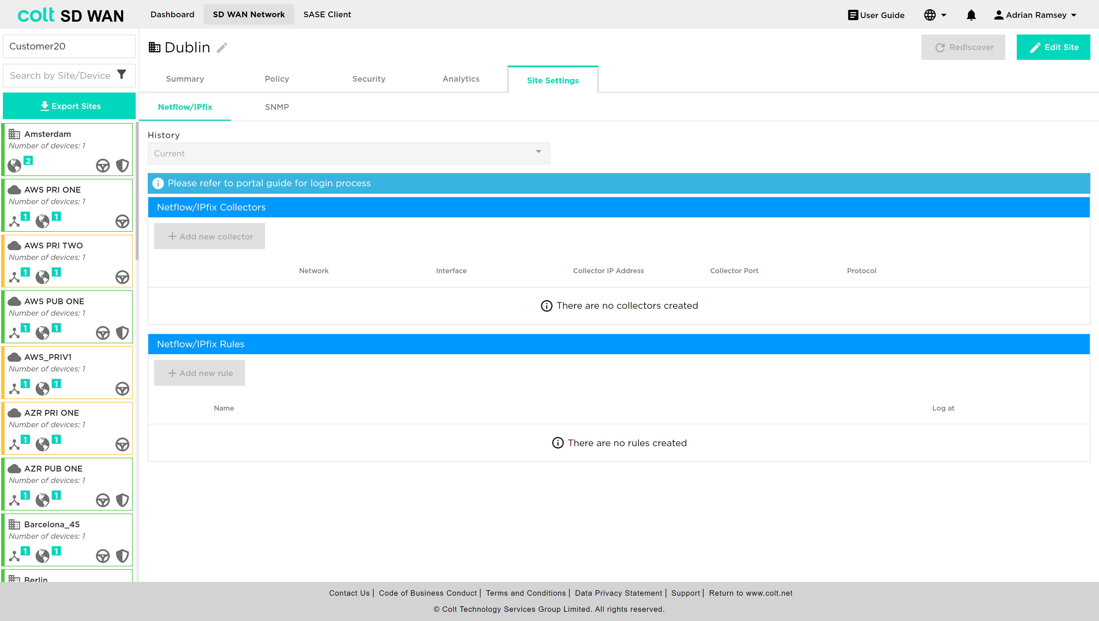
| For Netflow/IPFix we support collectors hosted in the Internet as well as within the customer´s network. If the customer site has local internet breakout enabled and the collector is not hosted in the Internet, to ensure logs are forwarded securely it is highly recommended to configure a deny firewall rule before any existing rules and also should match LAN-Zone(s) and the destination log collector IP. |
See the portal screenshots below:

The rule should be established as below:

There are two steps to provision a 3rd party log collector, the first is to configure the destination IP, port and protocol type per VPN or VLAN. This means multiple collectors can be provisioned. Note for IPFix the following collectors have been type approved by Versa:
-
Solarwinds
-
Cisco Stealthwatch
-
CA Technologies Netflow
|
Please note the following limitations:
|
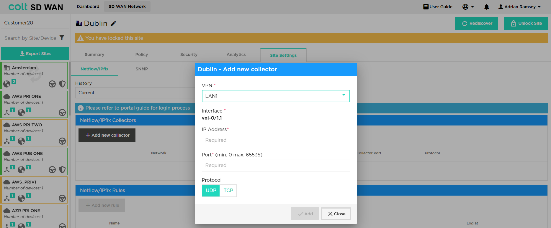
Note that when customer selects the relevant VPN, the related LAN interface is displayed on the portal – see above.
Forwarding of flow log files to a 3rd party collector can be filtered by creating rules with the following match criteria:
-
Log type (start and end or Interim)
-
Application or protocol
-
Source and/or Destination IP address
-
Source/destination Port or Port range
Log collector rules are applied to all Log collectors that have been created and the order of precedence can be set by the user I the same way as Policy or Firewall, by dragging the rule to the required position.
Bulk copy of Collector rules is also possible.
Start and end refers to logging at start and end of session. Interim means times when the flow is active for a long period of time there will be multiple log file. The default interim time is 1 minute - this time is not configurable.

SNMP Read Only
This feature allows access from a customer’s SNMP server allowing it to query specific MIBs on the SD WAN CPE device.
To add an SNMP server, the user should select Site Settings>SNMP, at which point the screenshot below will be visible. The user needs to input the device interface and the SNMP server IP. Below it, the user needs to set the SNMP authentication credentials – in this example a server with IP 1.1.1.1 is added to the LAN2 interface.
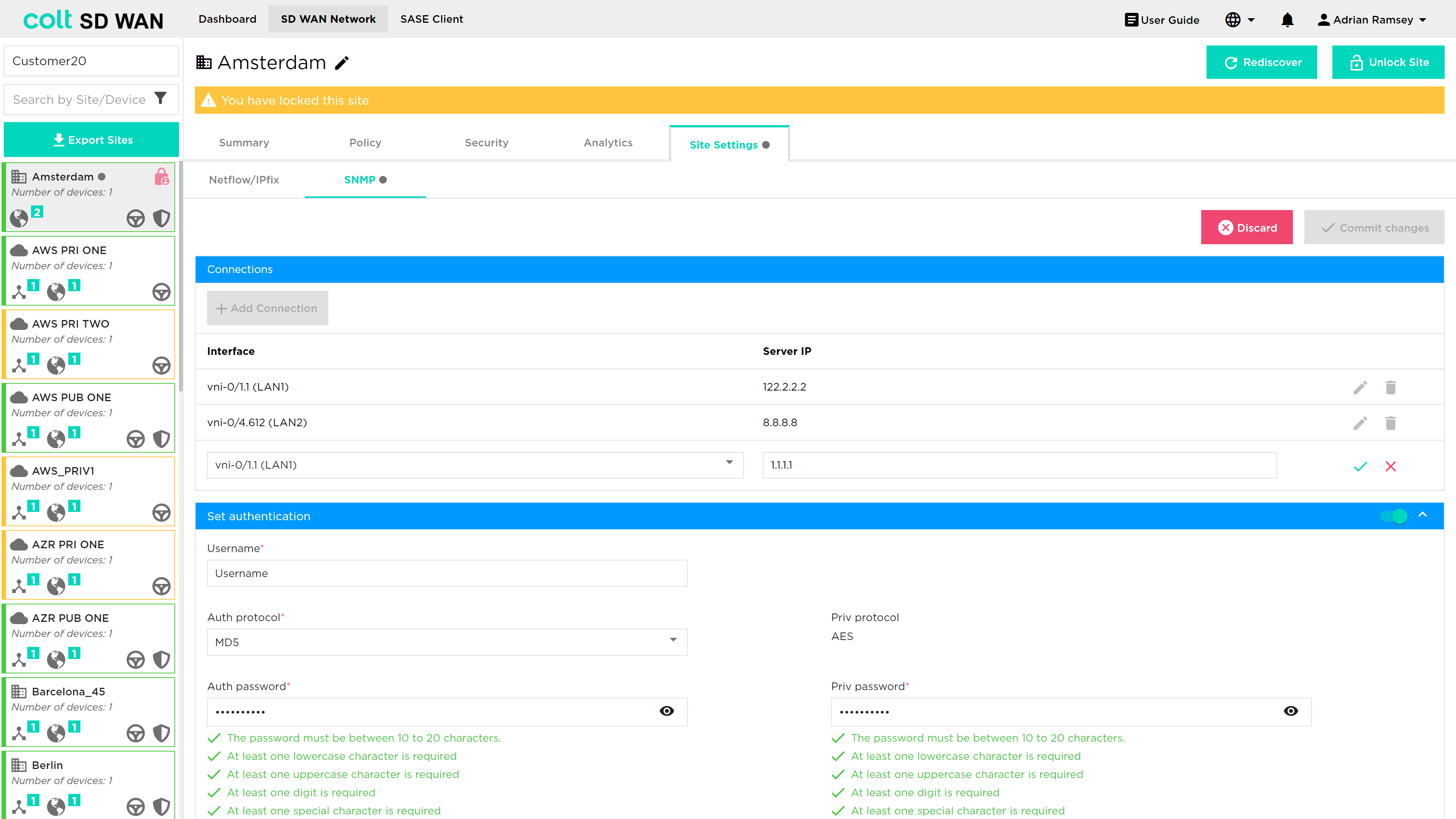
Once this has been actioned, the portal will display the following confirming that the server has been added correctly.